Getting shell on TP-Link TD864W modem/router combo
 Deniz Ariyan
Abstract
TP-Link TD864W is a modem/router combo that is widely used in Turkey mostly because it was given for free to every DSL subscriber by a major ISP in Turkey for years. Its software was modified for use by that particular ISP by TP-Link and is very limited on functionality especially when it comes to setting manual DNS and VPN settings. Today I am going to try to find a way into the shell of this modem/router combo firstly by correctly identifying the serial ports on the PCB, reverse engineering the pinouts with a basic multimeter, then connecting a USB UART so I can read the output and issue commands to the device from my computer.
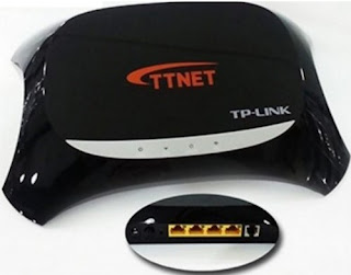
Figure 1. An external photo from market listings
Examining the board
Unfortunately, this device has no FCC filing so we have to take a look ourselves. When we take the very annoying plastic cover off and take a look at internal photos of the device we can see a very convenient 4-pin port which looks very much like a UART port (Outlined in red below in Figure 2). We can also see some chips which might come in handy later such as RTL8676 outlined in yellow and FL128SAIF00 outlined in blue in Figure 2.
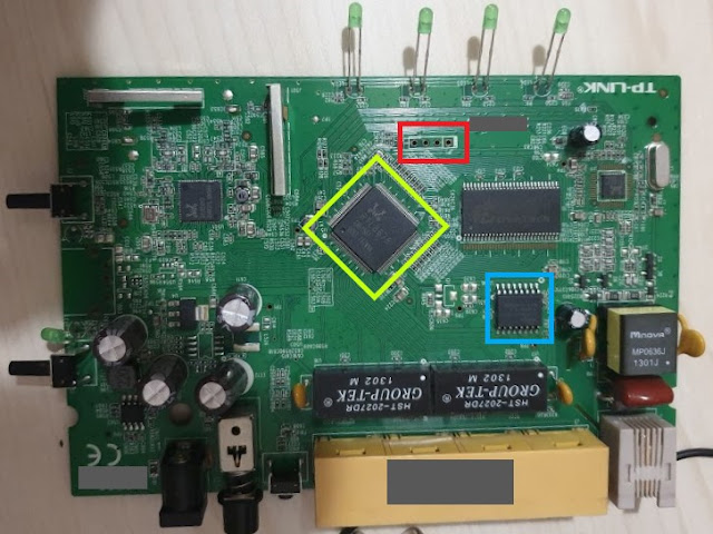
Figure 2. An internal photo of the device
Figuring out the pinout
Unfortunately, there is no standard for the UART pinouts therefore we will need to figure it out ourselves. There are different ways to identify the pinout of the port such as using a logic analyzer or a multimeter. Since I don't have a logic analyzer we will take the slower route and check every pin against R(ground), R(Vcc), and also watch their voltage range while the device is booting in order to identify their uses. But before we can do this we need a Ground and Vcc reference.
That's where the aforementioned RTL8676 and FL128SAIF00 chips come in handy. Since there is no way I'm gonna manage to freehand probe the pins on the RTL8676 (Outlined in yellow in Figure 2.) we are going to look for the datasheet of FL128SAIF00 (Outlined in blue in Figure 2.). If we take a look at the datasheet of FL128SAIF00, we can see that the pin-2 is Vcc and pin-10 is GND. We are going to use these pins as our Vcc and GND reference respectively while probing for our UART pins.

Figure 3. Close-up of the pins

Figure 4. Measurement results for the pins
Now that the measurements are done we can see that pin-4 is Vcc since it has zero resistance against Vcc and has a stable 3V3 output, we can also see that pin-3 is Ground since it has no resistance against GND and is always on zero Volts. This leaves us the pin-1 and pin-2 in which we have to decide which is TX and RX. The easiest way to do this is just to connect our multimeter in voltage measurement mode and check each pin while the device is booting. As long as the UART is not disabled, there will be a lot of output on the TX pin which means it will fluctuate in value. In this case, the pin-2 is TX since its voltage fluctuates between 1V7 to 3V3 during boot.
The best way to confirm our findings is to connect a USB UART interface and create a serial connection between our computer and the device.
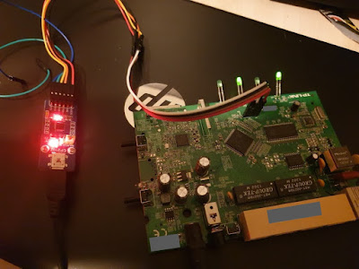
Figure 5. USB UART interface connected to the pins
Connecting to the device
After a mediocre solder work, we can connect our USB UART interface to the pins that we have identified earlier. Using a serial monitor such as PuTTY we can connect to our device. One thing that we still don't know about the connection is the baud rate. The best way to find the baud rate of a device is to just analyze it with an oscilloscope. Well, I don't have an oscilloscope lying around in my home so we will once again take the slower route and just try some common baud rates starting from 115200 because from experience this is what most of the routers I have seen run on.
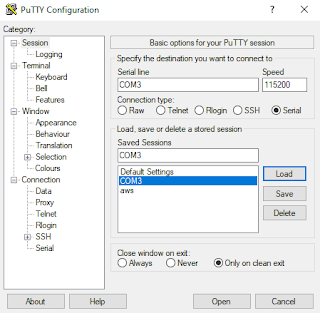
Figure 6. Settings for PuTTY serial connection
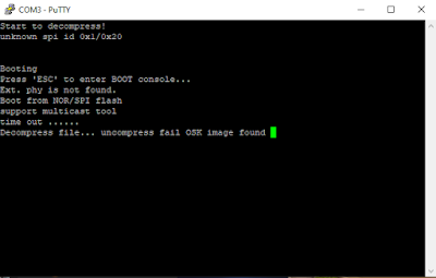
Figure 7. Boot sequence output
Thankfully we found the right baud rate on our first try, if you happen to be not as lucky as me you can check this question on the electronics Stack Exchange to get a better idea around the topic. And look what the 4th line says. Let's reboot and spam ESC until we get to the boot console.
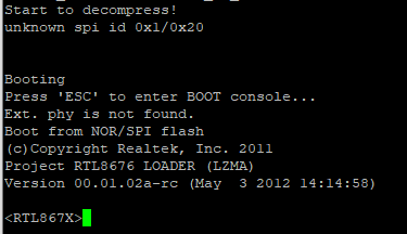
Figure 8. Entering the boot console
Well, that was easy. Let's see what we can do here in Figure 9.
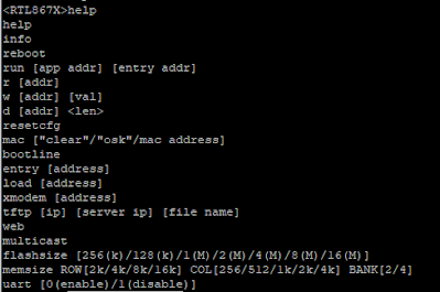
Figure 9. Boot console commands
Let's try the bootline first it is probably going to ask us to input a string, lets see if it has a limit on how many chars can be put on maybe we can do some easy buffer overflow here.
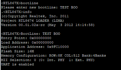
Figure 10. Bootline and info commands
Well, it has a set limit on the input so we are not going to get any easy buffer overflows here, we can later come back to this with edge cases if we need to. We also run the info command which displays some basic but very useful information about the device including our newly set bootline.

Figure 11. Displaying memory with d command
The d command takes a memory address and length parameter then displays the memory region for that address in cleartext. We can easily use this to dump the memory of the device for further research. You can find a basic Python script I wrote which takes the PuTTY log output and clears anything but the memory data and gives you a clean memory dump so you can use it for further research or reverse-engineering on my Github within one week from the publication date.
The rest of the commands in the boot console seems self-explanatory. They even gave us a TFTP command which we can use to flash a new firmware to the device from another host.
Subscribe to my newsletter
Read articles from Deniz Ariyan directly inside your inbox. Subscribe to the newsletter, and don't miss out.
Written by

Deniz Ariyan
Deniz Ariyan
Software Engineer, Maker