0x01-"Hello, World!" Program
 Asogwa Emmanuel
Printing "Hello, World!" to the console is the most basic operation there is in programming as it can be written in just about any programming language and is relatively simple to understand. The purpose of "Hello, World!" is to demonstrate a programming language's basic syntax and verify that the language is installed and working correctly on a computer.
Blinking LEDs can be considered the equivalent of a "Hello, World!" program in MCU programming. In this article, we officially write our "Hello, World!" program. I will demonstrate how to write the code for blinking the onboard LEDs using Board Support Packages. In later articles, we will see how to do this from scratch without library support.
Board Support Packages
A board support package (BSP) is a collection of software components that enables an operating system (OS) to run on a specific hardware platform. It includes device drivers, board-specific support libraries, and other software required to run the OS on a particular hardware platform.
Keil offers a range of tools for developing embedded systems, including a BSP builder tool called "Board Support Package (BSP) Builder". This tool allows developers to create a BSP for their specific hardware platform, which can then be used to run an OS on that hardware. Keil's BSP Builder supports various OSes, including popular options like Linux, VxWorks, and QNX.
Procedures
Create a new µvison project. Make sure to specify the appropriate target board.
Add ::CMSIS:CORE and ::Device:Startup software components to your project.
To add the Board Support Package for this project, open "Manage Runtime Environment" from the taskbar and expand "Board Support". We see that a couple of APIs are provided under it. For our application, we will only make use of the LED API. Expand this section and select the API as shown below.
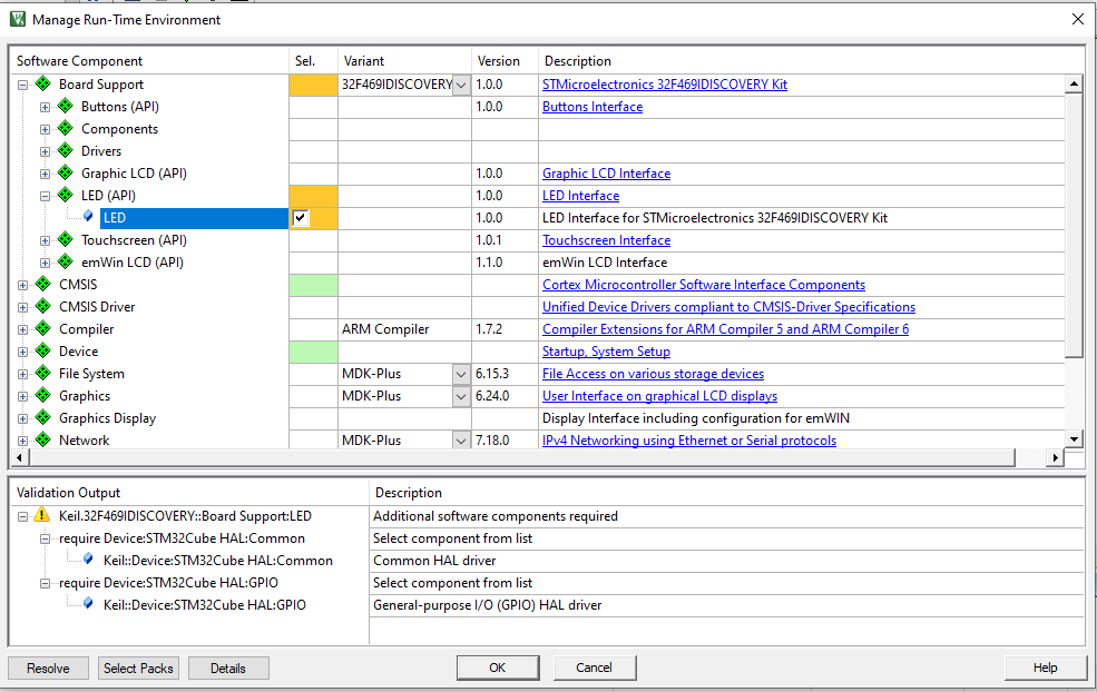
In the Output window, we observe a couple of errors. This is due to the absence of dependencies that the selected API depends on. Click "Resolve" to automatically add these dependencies.
Still, some dependencies were not added automatically. We have to add these manually. Proceed as follows:
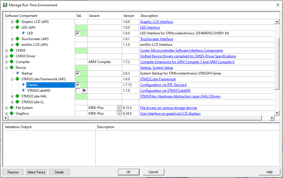
Now all the dependencies are resolved. "OK", and go back to the editor.
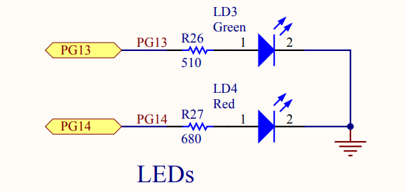
Before using the APIs we have added, we need to examine the schematics of the board we are working with. This will show us the pin names the LEDs are hooked up to enable us to address them adequately in the code. The easiest way of finding the part of the schematic of interest in the board manual is to find the name of the component on the board and search the board manual for it. In my case, the schematic looks like this:
Expand the "Board Support" from the project explorer and open the file under it.
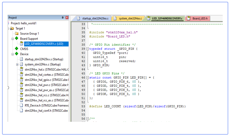
In the project pane, open the header file "Board_LED.h" under Board Support > LED_xxxx.c(LEDs) for inspection of the function prototypes the API exposes.
Create a C source file named main.c in your Source Group folder and open it up for editing.
//main.c
#include "Board_LED.h"
/**
The following functions are defined in the "Board_LED.h" header file. Study the description of each function.
extern int32_t  LED_Initialize   (void);
extern int32_t  LED_Uninitialize (void);
extern int32_t  LED_On           (uint32_t num);
extern int32_t  LED_Off          (uint32_t num);
extern int32_t  LED_SetOut       (uint32_t val);
extern uint32_t LED_GetCount     (void);
**/

#include "Board_LED.h"
int main(){
LED_Initialize(void);
//turn all the LEDs on
LED_On(0U);
LED_on(1U);
return 0;
}
The code above will turn on all the LEDs on the board. We can make things more interesting by blinking the LEDs one after the other.
#include "Board_LED.h"
#include <stdint.h>

//Simulate a delay
void delay(void){
for(volatile uint32_t i=0; i<500000;i++);
}

int main(void){
    LED_Initialize();
    //Repeatedly turn ON and OFF the two onboard LEDS
    while(1){
    LED_On(0U);
    delay();
    LED_Off(0U);
    delay();
    LED_On (1U);
    delay();
    LED_Off(1U);
    delay();
    }
    return 0;
}
Connect your board, navigate to "options for target" on the toolbar and set up the debug configurations. Finally, upload the code to your board and verify the LEDs are blinking as intended.
Further reading
Subscribe to my newsletter
Read articles from Asogwa Emmanuel directly inside your inbox. Subscribe to the newsletter, and don't miss out.
Written by

Asogwa Emmanuel
Asogwa Emmanuel
As an Electronics and Communications undergrad, I am deeply interested in the design of embedded systems in programmable logic, robotics and problem-solving. These domains excite me and drive my passion for learning and creating innovative solutions.