ESP-07 beginner's guide
 Milan Lazarević
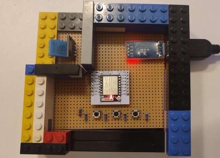
ESP-07 features an ESP8266 microcontroller with a built-in ceramic antenna and an optional external antenna port. It operates on 3.3V and will be damaged if connected to 5V. The board comes with pre-installed AT software that enables control over serial port communication. You can also program the board using the Arduino IDE with a set of networking libraries for the ESP8266.
Connecting to the serial port on the PC
To connect the ESP-07 board to a PC, we need a programmer device that acts as an intermediary for communication. In this tutorial, I will be using the Arduino Uno board as a programmer.
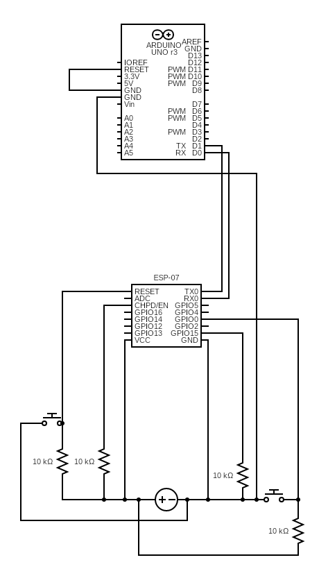
The circuit diagram for connecting the ESP-07 to the Arduino Uno is shown in the image below. By connecting the reset and ground pins on the Arduino, we disable the built-in microcontroller on the Arduino and pass all the communication to the ESP-07 instead.
Although the Arduino Uno has a 3.3V output, it is not recommended to use it for powering the ESP-07 as it may be unstable. An external 3.3V power source is advised instead.
The diagram shows two buttons. The left is for resetting the device and the right is for flashing code to the device (this will be explained in more detail later).

Serial port communication over PC
The next step is to install the Arduino IDE on your PC if you haven't done so already. You can download the installation on this link: https://www.arduino.cc/en/software
Once you have installed the Arduino IDE, you can connect the Arduino to the PC using a USB cable and turn on the external power supply for the ESP-07. Then, open the Arduino IDE and click on the serial port communication icon in the top right corner.

In the Serial Monitor window, you will need to configure the drop-down menus in the top right corner as follows: Both NL & CR, 115200 baud (use 74880 baud if you want to see debug logs of the board).

You have completed the setup for the ESP-07 device. To test its functionality, you can use the AT command and check the response from the device. For example type "AT" and OK return should be prompted if everything is working correctly.

The following commands are also available for further exploration.
| Command | Description |
| AT | Is the device running correctly |
| AT+RST | Reset the device |
| AT+GMR | Firmware versions |
| AT+CWMODE? | Which WiFi mode is set: 1 - Station (connect to other WiFi), 2 - Access Point (run WiFi network), 3 - Hybrid. |
| AT+CWMODE= | Change WiFi mode |
| AT+CWLAP | Check available networks (Requires mode 1, 3) |
| AT+CWJAP=”SSID”,”PASSWORD” | Connects to the specific network |
| AT+CIFSR | Display obtained IP address |
| AT+PING=”IP ADDR” | Ping specific IP address |
| AT+CWJAP="","" | Disconnect from the connected network |
If you made it to this part, you have a fully functioning setup that can execute pre-installed firmware commands Through a serial port.
Flash your code to the ESP-07
In this step, you will go through the installation of the necessary drivers, and steps required for flashing your code from ArduinoIDE to the board.
To compile the code for the ESP-07, we need to install some packages in the Arduino IDE. Follow these steps:
Go to File → Preferences
In the Additional Boards Manager URLs field, enter the text line below
http://arduino.esp8266.com/stable/package_esp8266com_index.jsonClick OK
Go to Tools → Board → Boards Manager
Type ESP8266 and install the package
Go to Tools → Board and select Generic ESP8266 Module
You have successfully configured the Arduino IDE for the ESP-07 device.
To upload the code to the ESP-07 device, you need to enable the Flashing mode first. Follow these steps:
Push the flash button
Push the reset button
Release the reset button
Release the flash button
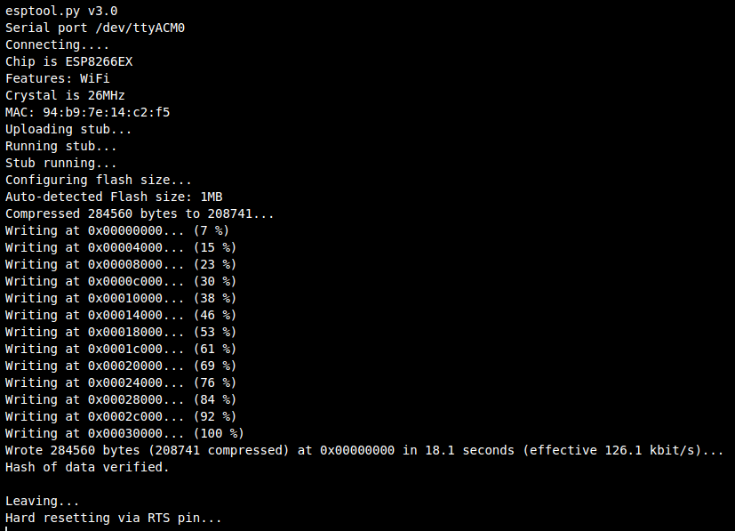
The device is now ready to receive the code from the Arduino IDE. Click the upload button to start the process.

To run the code on the device, you need to restart it by pressing the reset button. The code will execute automatically after the device reboots.
Additional content
If you are seeking inspiration for fun and innovative projects utilizing the ESP07 module, consider exploring my Weather WiFi Station repository. This repository showcases a project that utilizes the ESP07 board to collect and transmit weather data over WiFi, making it an excellent starting point for those interested in sensor networks and Internet of Things (IoT) applications.
https://github.com/MrLaki5/ESP8266-weather-wifi-station
Subscribe to my newsletter
Read articles from Milan Lazarević directly inside your inbox. Subscribe to the newsletter, and don't miss out.
Written by
