I want an electric bicycle!
 L.
L.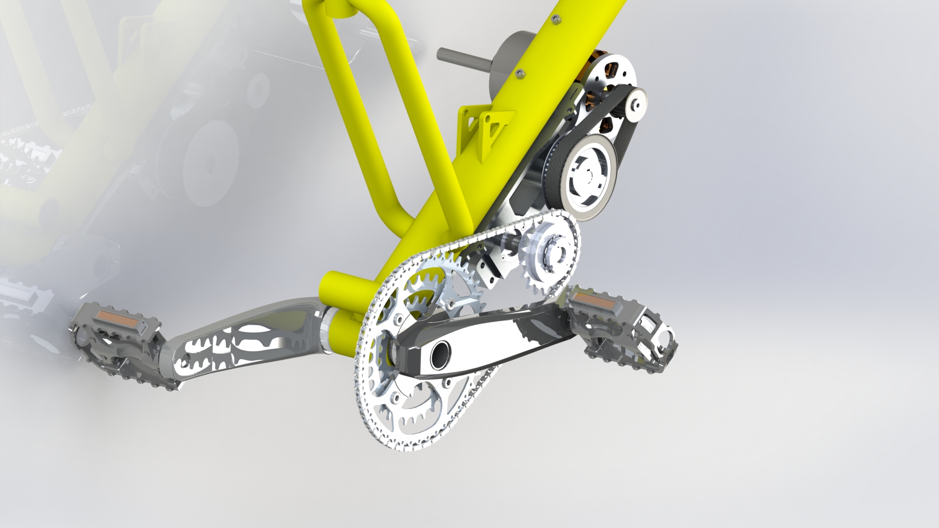
I want to share my experiences and knowledge in the fields of engineering, electronics, and mechanics. As a passionate engineer, I’ve always been fascinated by how different disciplines overlap and complement each other. What better way to explore this than through a hands-on, self-directed project like building a homemade electric bicycle?
Back in 2014, I decided to build my own electric bicycle. At the time, electric bike regulations in Germany were still developing, offering an opportunity to experiment freely on public roads. This gave me the freedom to build something based entirely on my vision—without worrying about compliance limitations.
My aim with this post is to share practical knowledge, inspire other engineers and hobbyists, and demonstrate how personal projects can blend mechanics, electronics, and embedded systems into something tangible.
Why Build It Yourself?
That question comes up a lot. But for me, understanding how things work has always been the driving force. During my research, I came across several impressive DIY builds—especially from Knoxieman on YouTube—which motivated me to start my own. Commercial systems at the time were limited, often requiring imports from China, and I wanted full control over both the design and functionality. Building from scratch was the most direct way to learn.
Requirements are always needed
From the beginning, I defined some core requirements:
Maximum speed of 50 km/h for security reasons.
The minimum range of 20 km on half throttle.
Adaptable power output and speed configuration.
Emphasis on low gravity mass for stability.
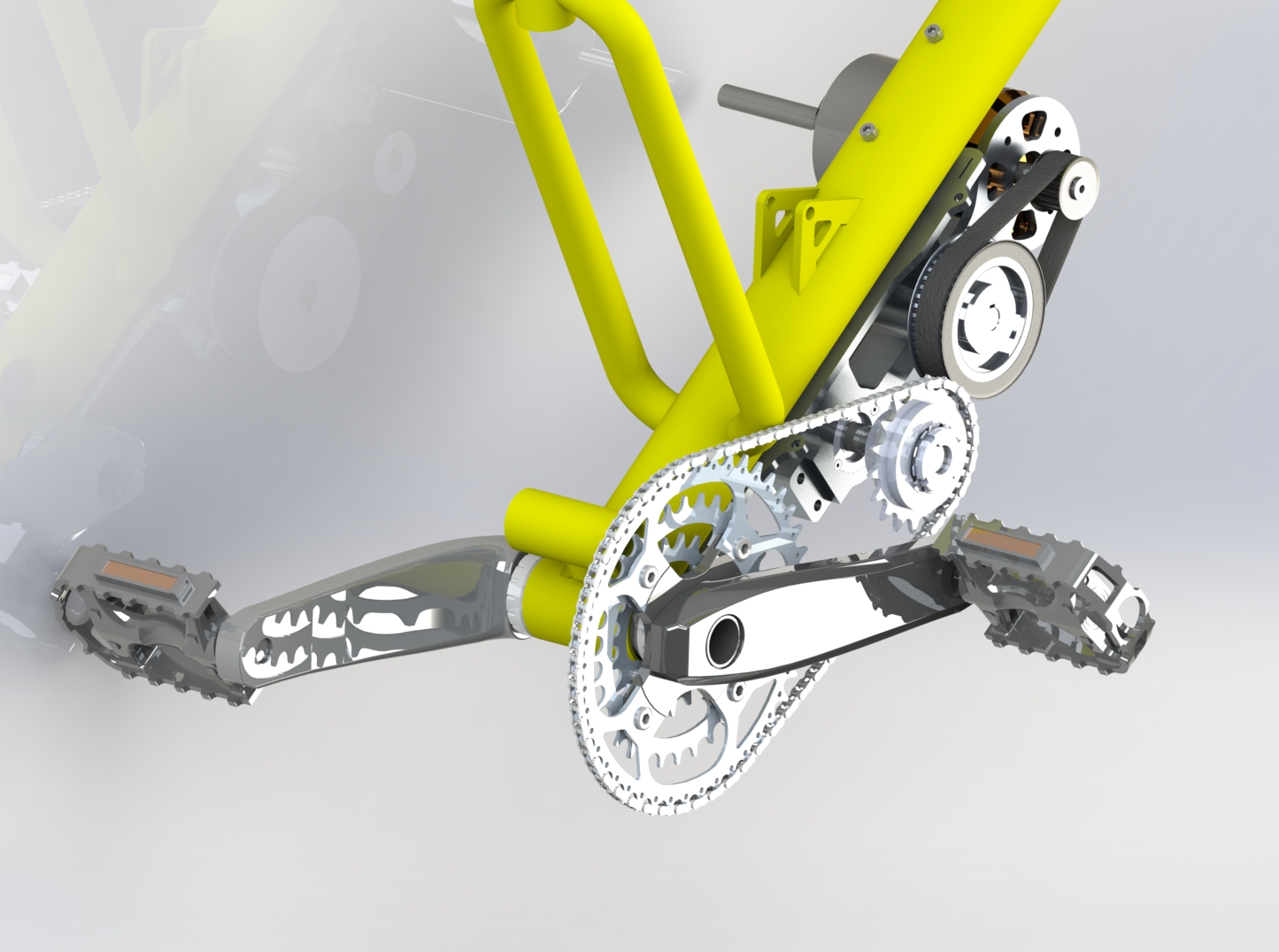
During the design process, I considered different propulsion systems, specifically the mid-drive and wheel-driven systems. Evaluating their advantages, I decided to opt for a mid-drive system. This choice allowed me to leverage the bicycle's existing gearing, providing enhanced flexibility and efficiency in the driving system.
Incorporating a mid-drive system meant that power was delivered directly to the crankshaft, utilizing the bicycle's gears to optimize performance. This design allowed for better utilization of the available power and provided a more natural riding experience. The flexibility of the mid-drive system also enabled me to fine-tune the power output and speed configuration to suit various riding conditions.
Throughout the integration and testing phases, I paid close attention to the compatibility and alignment of the mid-drive system. By carefully aligning the motor and the bicycle's existing gears, I achieved seamless integration, allowing for smooth power transfer and efficient energy utilization.
The design and planning process took into account the benefits of using a mid-drive system, leveraging the bicycle's gearing to enhance flexibility and optimize the driving system's performance. This decision played a crucial role in achieving the desired speed, range, and adaptability of my self-made electric bicycle.
Planning the development process
I mapped out a procurement strategy spanning the USA, UK, Germany, and China, using a critical-path approach to reduce delays.

Planning the system
A visual diagram helped define additional system needs, especially around the control electronics.

Visual system planning helped me spot dependencies early—especially for the control board, which I built myself to support nearly closed-loop speed/power control.
| Must-Have Features | Achievement path |
| -Speed Control | Integration of a speed sensor (hall-sensor) on the rear wheel. |
| -Temperature Control | Integration of temperature sensors into the ESC (Electronic Speed Controller) and motor. |
| -Wide input voltage range | Initially planned to be achieved through a Buck converter, later resolved by VESC integration. |
| -Undervoltage protection and alarm | Measurement through a voltage divider and integrated 10-bit ADC. |
| Nice-to-Have Features | |
| -Anti-Theft Alarm | Integration of an accelerometer sensor into the control board. |
| -Power Output Management | Initially planned to be integrated into the control board but later limited by the VESC. |
| -Optimal Gear shifting panel | Cross-analysis of speed and current values measured through the shunt. Allows for determining the best moment for gear shifting. |
After the initial requirement analysis, I specified the necessary inputs from the control board. This helped me determine the appropriate microcontroller to use later on.

Calculate, calculate and calculate
When designing the adaptable power output and speed configuration, I considered various parameters to ensure optimal performance.
By incorporating these parameters into calculations and simulations using Excel, I evaluated the impact of each variable on power requirements and speed ranges. This comprehensive approach allowed me to fine-tune the design and optimize the adaptable power output for different riding conditions.
Through iterative calculations and simulations, I considered the interplay between weight, wheel radius, rolling resistance, aerodynamic factors, and hill gradients to determine an optimal power output and speed configuration. This holistic approach ensured that the electric bicycle could efficiently and effectively perform across different terrains and scenarios.

On a 12S system (44.4V and 10Ah) and in second gear, I projected a maximum range of 72.9 km! If you wish to get the Excel file I used during the development process like this post and write me up. Please note that it has not been optimized or cleaned up before publishing. If you wish the file make sure you like this blog post. It will provide valuable insights into designing an electric bicycle.
3D-Modelling and iterations
Just like in life, I started with small steps during the 3D modelling process.
I put a lot of thought into the mechanical system, including considerations for part strength, system clearance, bearing press-fit calculations, and stress testing. The system had to be flexible enough to be implemented in other applications, so I took into account a certain degree of system flexibility for future improvements, including different mounting systems.
Some of the calculations can be found on the second sheet of the Excel file mentioned earlier.

The resulting frame was intentionally overbuilt to handle up to 7 kW of power. Although I could’ve reduced mass by about 0.5 kg, the complexity and cost weren’t worth the trade-off.
The final CNC-milled version of the central drive turned out to be highly optimized, with press-fitted bearings that could handle more than twice the original system stress. I could have significantly reduced the mass of the part, but that would have meant higher milling costs/complexity, and the weight reduction would have been only around 0.5 kg, which can be easily ignored.
Exploded View:
A video of the initial assembly of the system:
Parts, parts and more parts
The central part was CNC-milled from a 7075 aluminium block, while the sheeted parts (motor mounting, upper base, and bearing holders) were laser-cut (6082 aluminium) by a manufacturer in Germany.
Most of the electrical system parts were ordered from Germany, while the Motor (Alien Power Systems) and VESC (Electronic Speed Controlled) were obtained from the UK. Some key parts, like the freewheel, were directly ordered from the USA due to their limited availability. Originally, such freewheels are used on Chainsaws in the USA.

Each of these parts had its own set of requirements, which were carefully considered during the development and ordering process.
Setting up the electronic development
To develop a control board specific to my needs, I created a development mockup to program the inputs and outputs into the microcontroller accordingly.

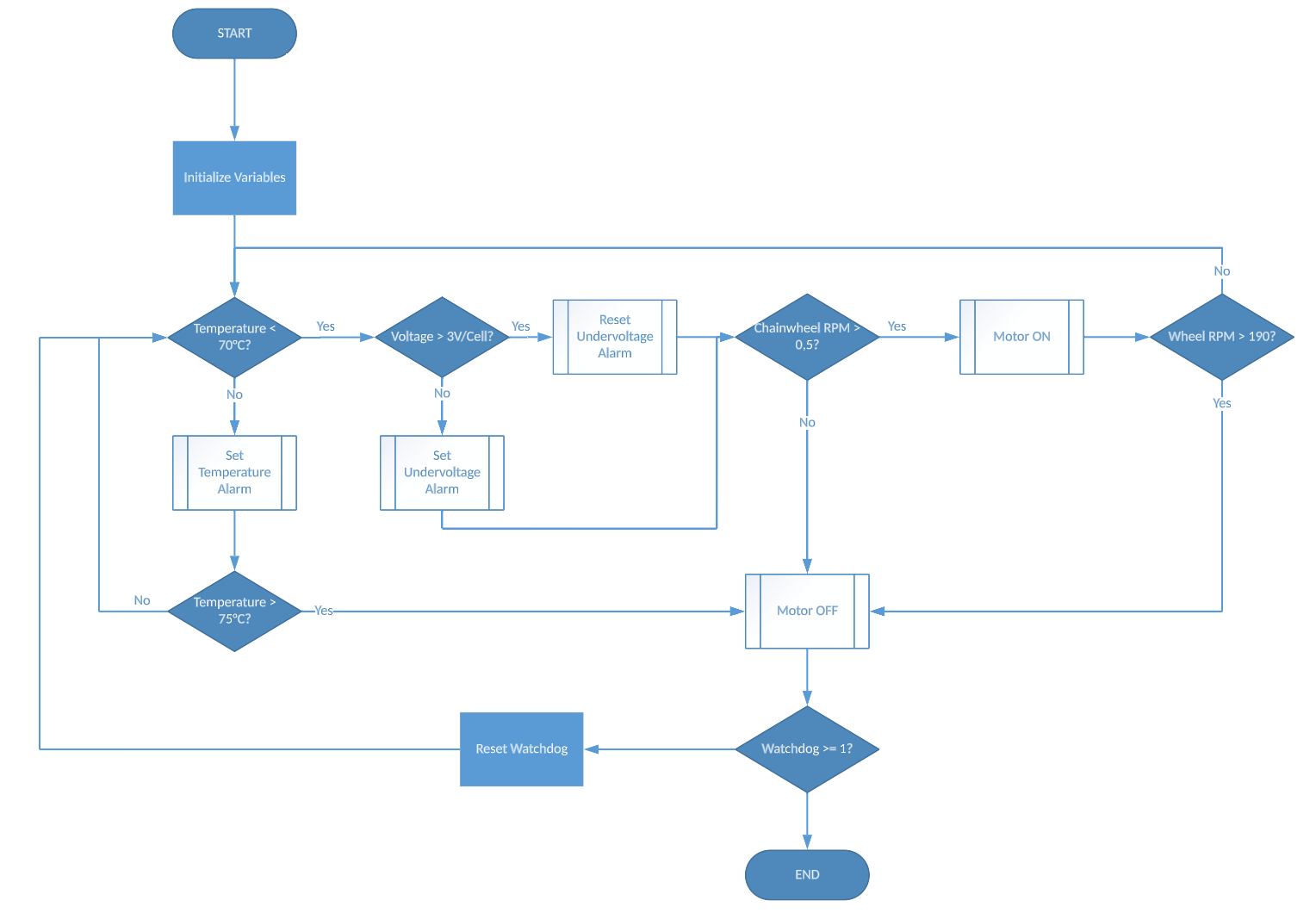
Logic for the microcontroller firmware was sketched early on:
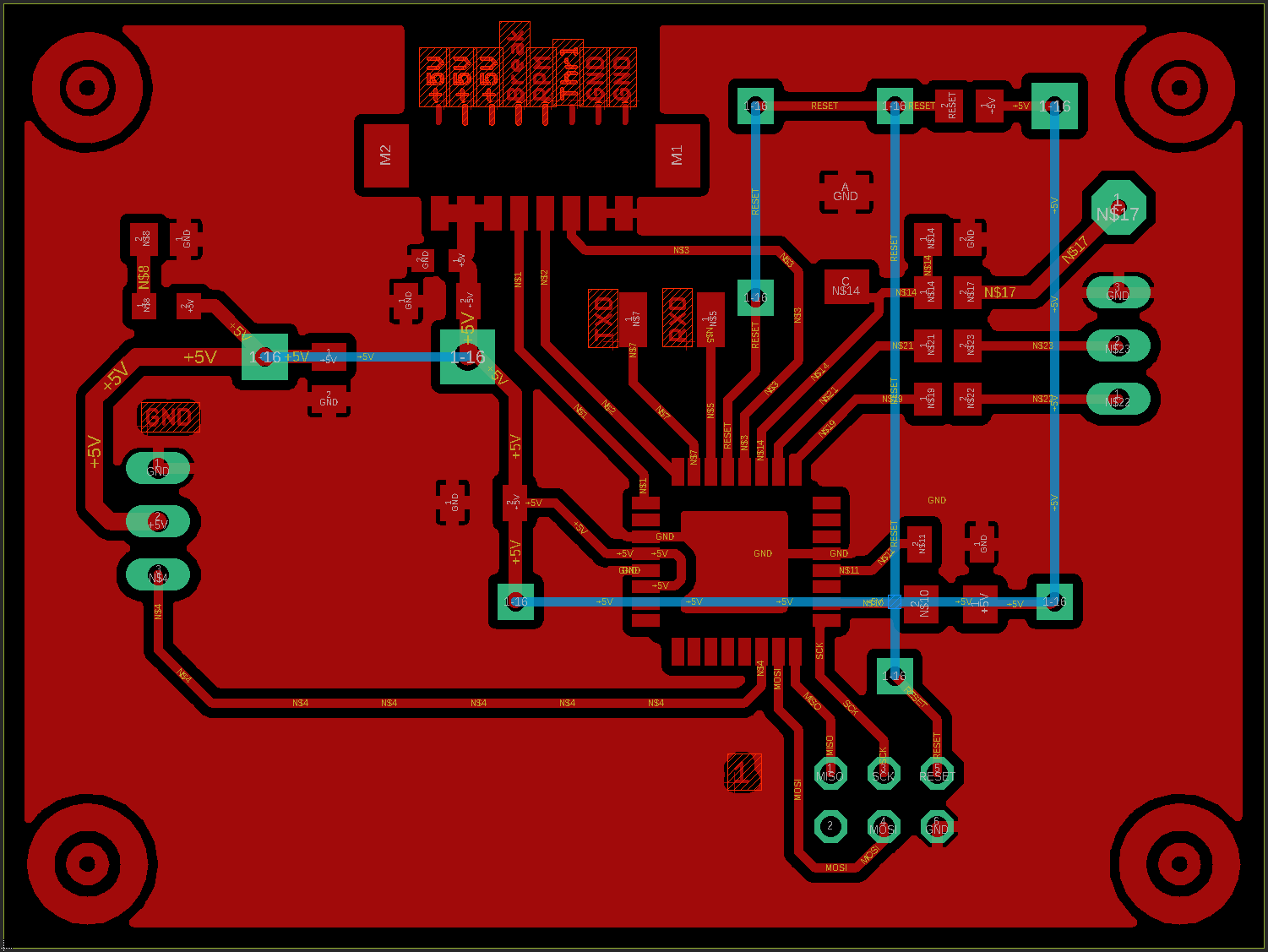
The speed control board was developed using EAGLE. Originally, I planned to have a separate Buck converter as a power source, but this requirement changed since I was using a highly advanced ESC that provided an independent and stable 5V source. Future versions of this board would need to operate independently since an error in the ESC would result in the control board turning off automatically. Having a standalone power source would allow me to add functions like an Anti-Theft system that remains on at all times and create a certain level of system redundancy.

Initial firmware was written in BASCOM using an Atmega8. While it lacked I/O capacity for the final version, it was enough for testing. Later iterations used the Atmega32.
Yes, BASCOM is somewhat inefficient, but for small-scale home projects, it worked fine.

Final toughts
This project allowed me to explore system integration across mechanical, electrical, and software domains. Building a functional electric bicycle from scratch provided valuable hands-on experience and helped me understand the full development cycle—from concept to working prototype.
I hope this documentation encourages others to take on similar projects. If you're thinking about building something from scratch, start simple, plan thoroughly, and don’t be afraid to adapt along the way.
Thanks for reading.
Subscribe to my newsletter
Read articles from L. directly inside your inbox. Subscribe to the newsletter, and don't miss out.
Written by