Introduction of IAR Visual State - 1
 Hyunwoo Choi

In General, the firmware executes certain tasks periodically. Blinking a LED is the "Hello World" in the firmware world. Even this simple functionality is doing something periodically. This pattern can be easy to represent by using a state machine. To blink a LED, it would need two different states (On and Off). Every given period, it will switch the state from on to off or from off to on. IAR Visual State is used to graphically design state machines based on UML and generate C, C++, C# or Java source code.
The following materials are based on IAR Visual State's "Getting Started".

I am going to implement a traffic light that would have three different states (Red, Yellow, and Green). The first step is to define the states. The second step is to define transitions. The third step is to define the event between transitions. The fourth step is to define the action between transitions.
Before place, the states, workspace and project need to be created.
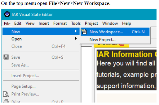
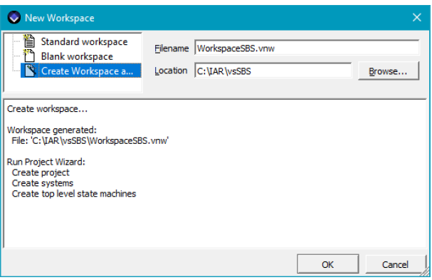


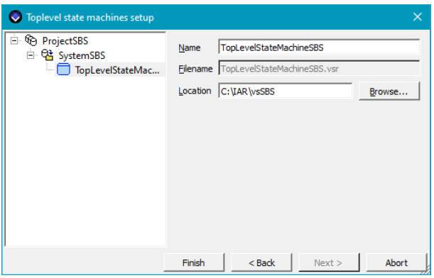
Let's add three states. To create a simple state, click highlight one below:

Then click Region1 three times.
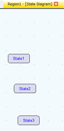
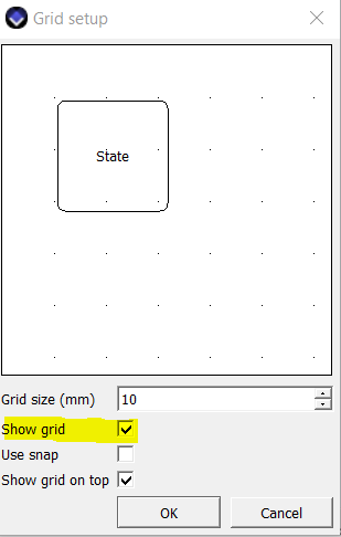
Few minor tips to show the grid and alignment.
Tools>Grid Setup...> Check "Show grid" to activate it
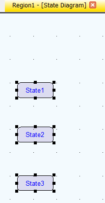
Select all three states highlighted below:
Format>Alighment>Center Horizontal
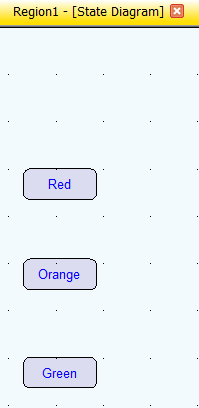
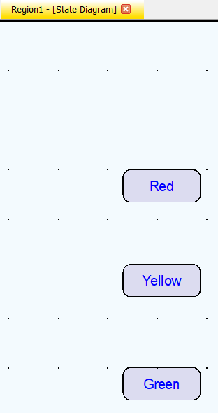
Double click text inside of state and rename each state as Red, Yellow and Green.
Add all possible transitions using the transition tool highlighted below:

Click source and then click destination to generate a transition.
Add initial transition to Red state using the Initial state tool and transition tool highlighted below:


Add two events.
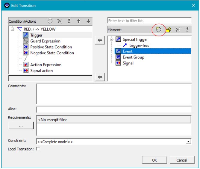
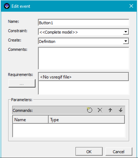
Then also add Button2
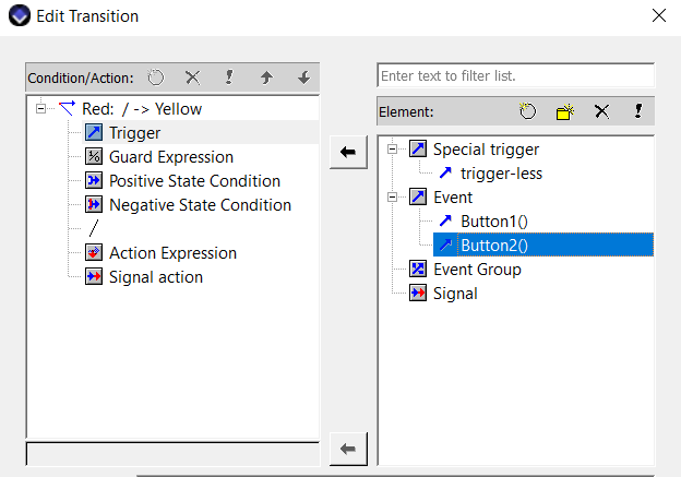
Add Button1() from Yellow to Red by double-clicking Button1().
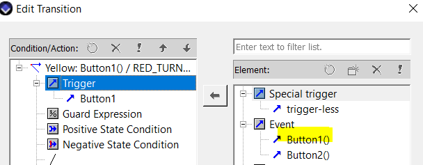
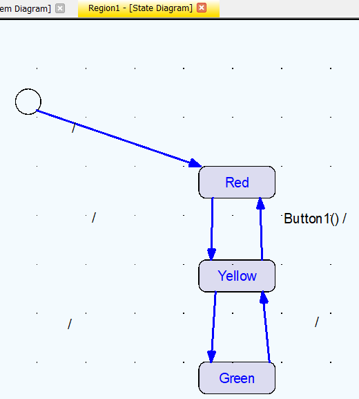
Add Button1() from Green to Yellow by double-clicking Button1().
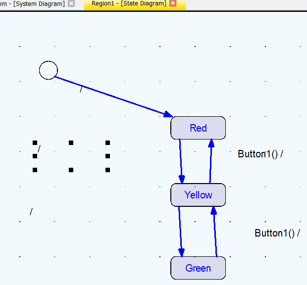
Add Button2() from Red to Yellow by double-clicking Button2().
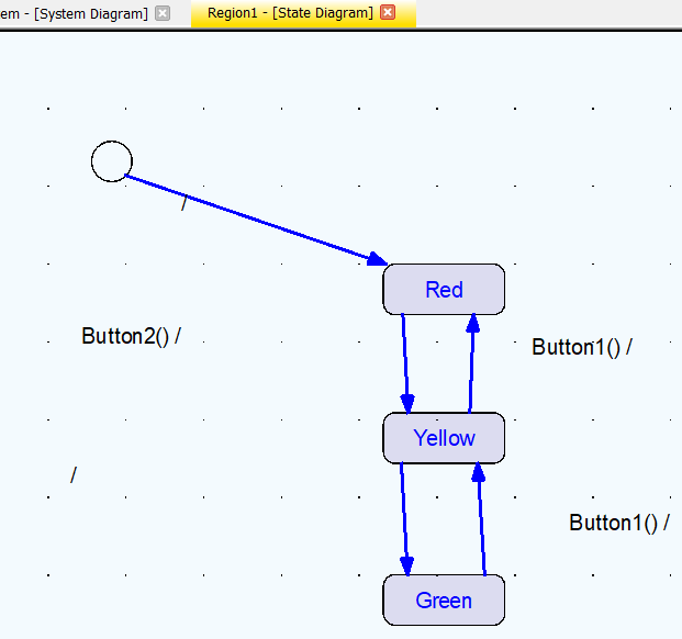
Add Button2() from Yellow to Green by double-clicking Button2().

Add three actions: YELLOW_TURN_ON(), GREEN_TURN_ON(), RED_TURN_ON().
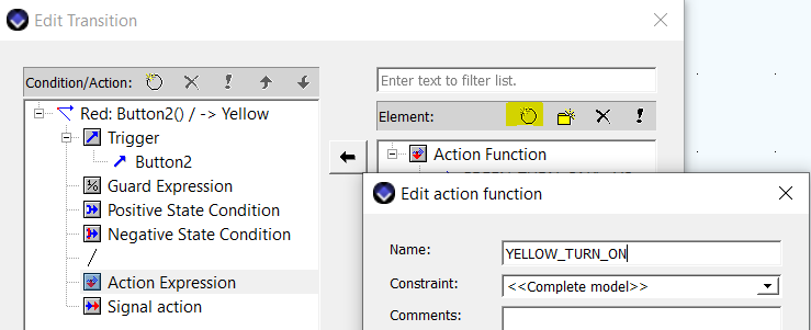
Add YELLOW_TURN_ON() from Red to Yellow by double-clicking YELLOW_TURN_ON().
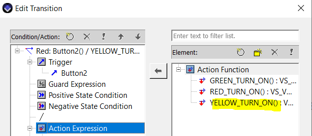
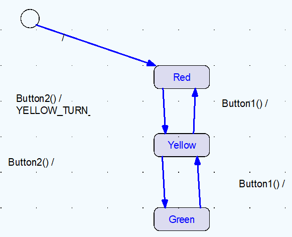
Add YELLOW_TURN_ON() from Green to Yellow by double-clicking YELLOW_TURN_ON().
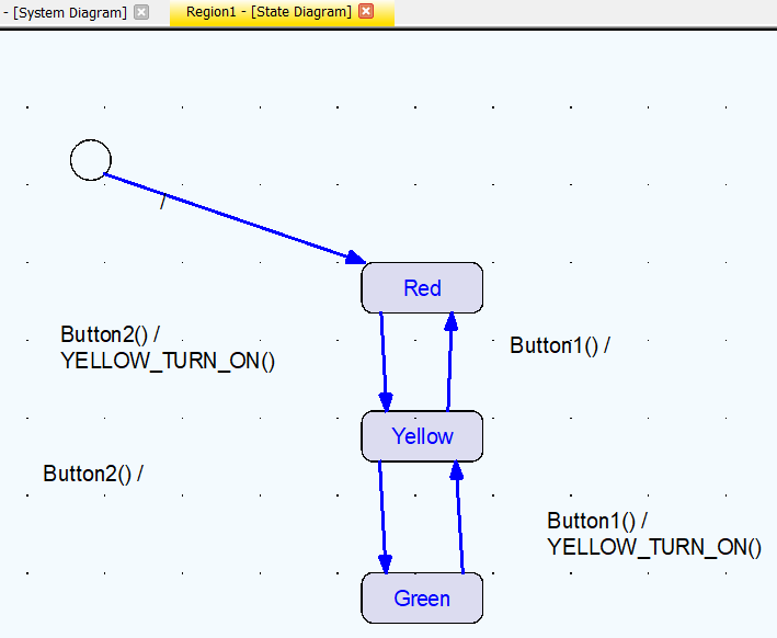
Add RED_TURN_ON() from Yellow to Red by double-clicking RED_TURN_ON().
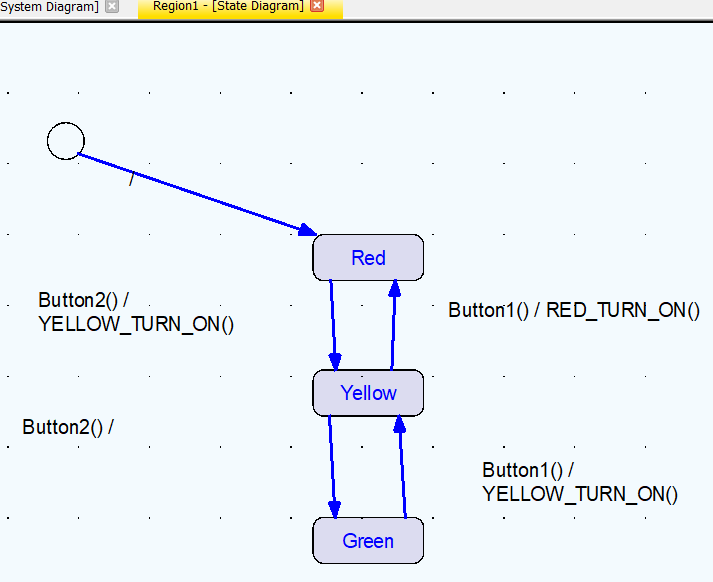
Add GREEN_TURN_ON from Yellow to Green by double-clicking GREEN_TURN_ON().
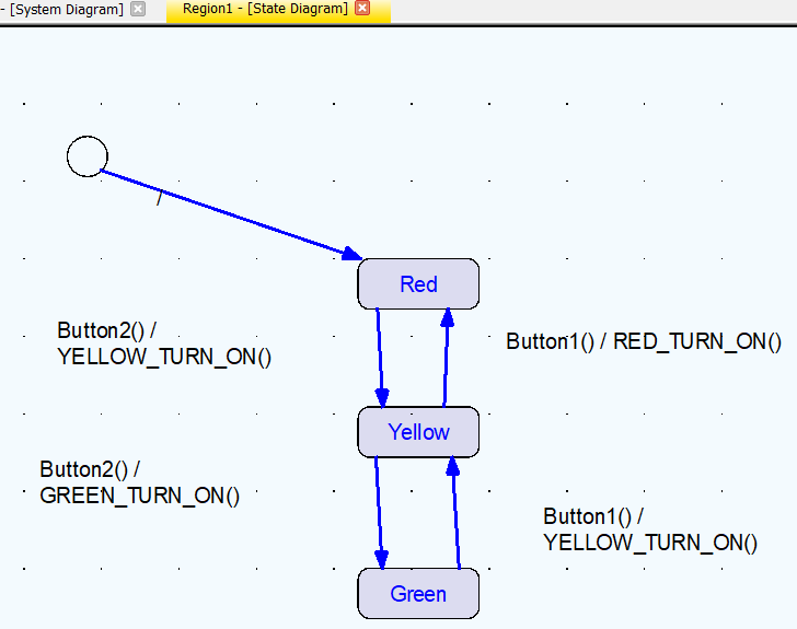
Add RED_TURN_ON() from Initial to Red by double-clicking RED_TURN_ON().
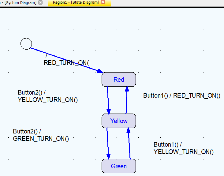
Finally, all four steps are covered and the state machine is completed above. The first step is to define the states. The second step is to define transitions. The third step is to define the event between transitions. The fourth step is to define the action between transitions. Next time, I will go through generating code and verify the design with the simulator and verify the design issue.
Subscribe to my newsletter
Read articles from Hyunwoo Choi directly inside your inbox. Subscribe to the newsletter, and don't miss out.
Written by
