Aviatrix Network Segmentation
 Karim El Jamali
Background on Network Segmentation
Network Segmentation (a.k.a VRFs) is a common theme in large enterprises and service providers.
Service Providers use segmentation at their Provider Edge (PE) routers whereby those PE(s) connect to multiple Customer Edge (CE) routers while maintaining separate routing domains for each of those customers.
Enterprise environments generally have a multitude of services (Data, IP Telephony, IoT, CCTV, IPTV…etc) whereby each service can run on its own dedicated infrastructure or have them all share a common infrastructure. In addition, multiple applications running on-premises and cloud have strict compliance and security requirements on segmentation & isolation. One example of compliance requirement is The Payment Card Industry Data Security Standard (PCI DSS) which sets a widely accepted set of policies and procedures intended to optimize the security of credit, debit and cash card transactions and protect cardholders against misuse of their personal information. PCI DSS strongly recommends network segmentation or isolating the cardholder data environment from the rest of the network. On another note, the majority of customers run development and production environments and it is imperative for security, operations and compliance reasons to keep both environments isolated. Finally, overlapping addresses as a result of mergers & acquisitions (M&A) or poor planning are a common reality and at many times are dealt with via network segmentation and/or NAT.
One of the concerns of a common routing domain is a large blast radius whereby any problem involving routing injection or deletion could result in outages across all of these services. In addition, a common routing domain allows attackers to target specific IoT devices with a lower security posture and use those IoT devices to sneak into the crown jewels within the environment. Since most of these services operate independently of one another, a proper security policy would be to isolate them from one another thus improving the environment’s security posture.
Cloud Network Segmentation
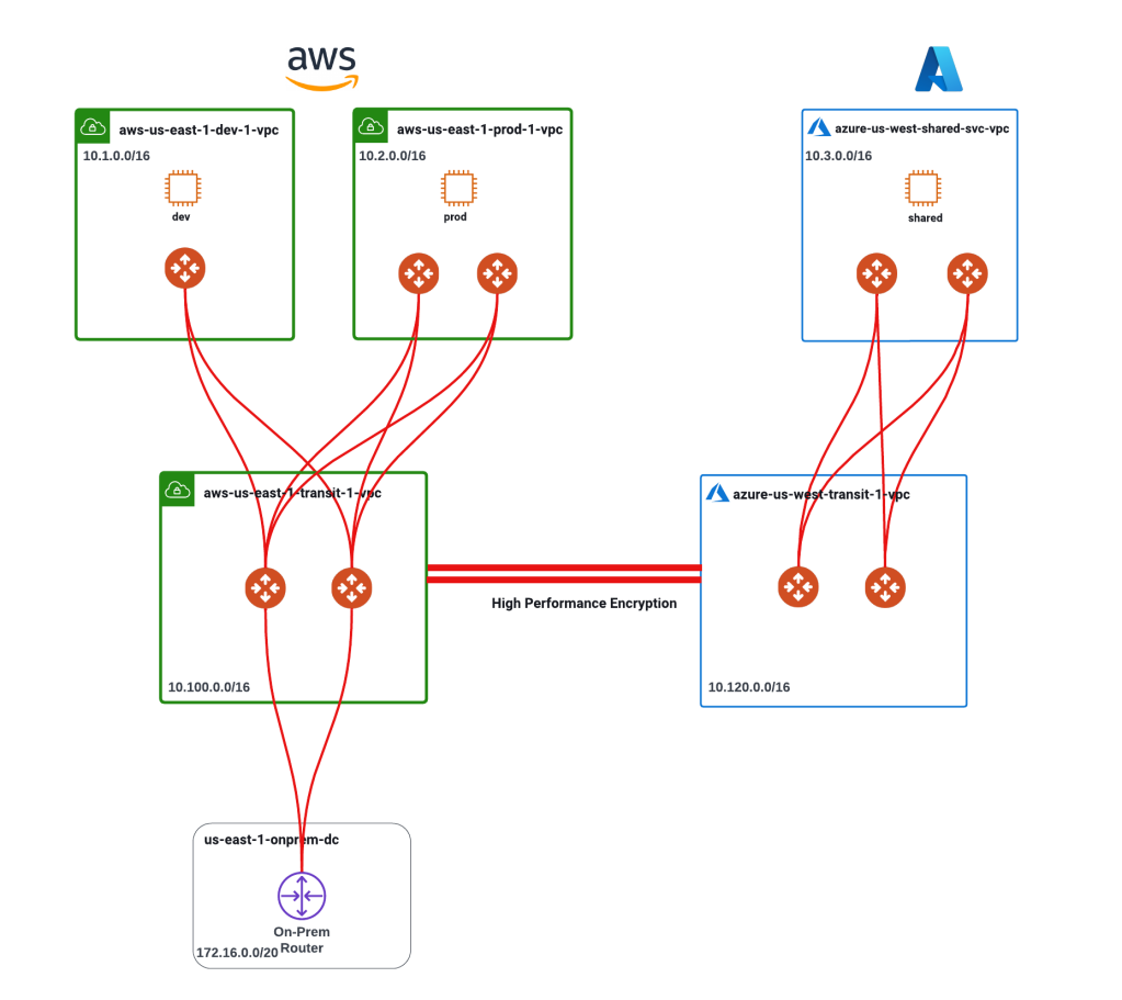
Let us start by looking at the below diagram. The diagram shows:
2 CSPs (AWS, Azure) and an on-prem environment.
3 Virtual Machines (dev, prod and shared) in each of the spoke VPCs.
If you would like to better understand the architecture, you can have a look here.
Without network segmentation, we operate in a common routing domain i.e. there is a common routing table for dev, prod and shared services allowing routing reachability between all 3 workloads. This however, doesn’t always equate to data plane reachability as there are security constructs that can be leveraged to block this communication (Security Groups, Network Security Groups, NACLs, Firewalls).
Common Routing Domain Explained
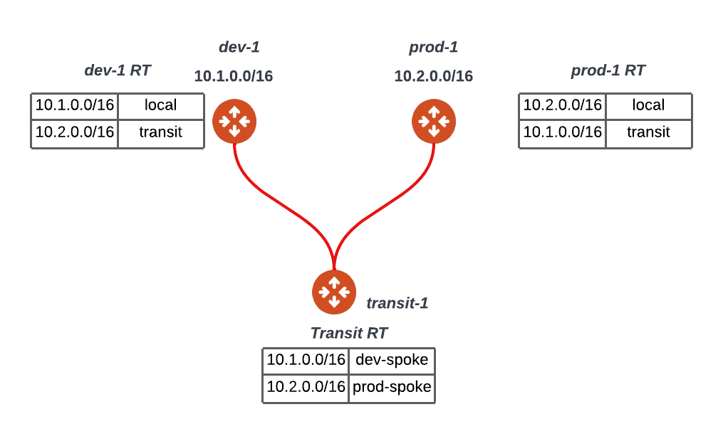
The below diagram dives a bit further into the common routing domain (i.e. no segmentation). I have removed the workloads for simplicity, thus we have two spoke gateways (dev-1 and prod-1) connected to a common transit (transit-1). Note that in this setup, the transit has a common/default routing table that gets shared with the dev-1 and prod-1 spokes allowing any-to-any routing reachability.
Segmenting the Network
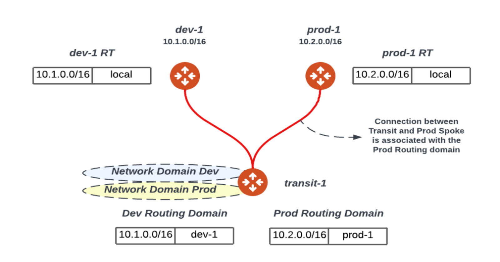
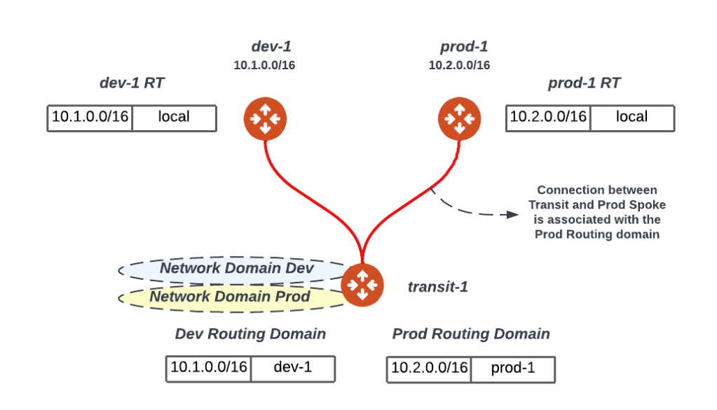
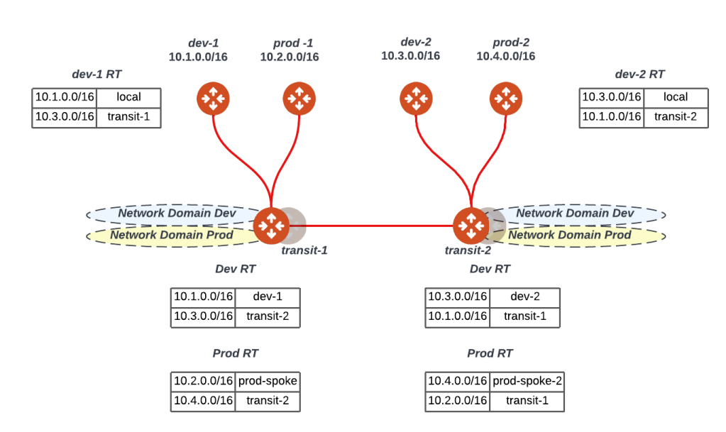
The below diagram segments the infrastructure to two network domains (Dev/Prod). Please note the following:
Transit routers will have all the routing tables (similar to a PE router) or Network Domains (Dev/Prod)
Upon attaching a spoke gateway (e.g. prod-1) to the transit gateway (transit-1) the transit gateway will associate the spoke gateway with a Network Domain (Prod) limiting its view of the world to the Prod search space or routing table. In this example, when traffic reaches the prod-1 GW from the prod instances they will be subject to the prod-1 routing table thus no communication is possible between prod & dev workloads.
It is important to realize that that this segmentation takes place at the transit layer i.e. any connection to the transit where the transit is enabled for segmentation can be associated or placed in a network domain limiting its search space.
Extending Segmentation to other Regions and Clouds
The below figure expands the same logic to another transit. Two important points to recall here:
All the segmentation we are talking about here is CSP agnostic and can extend to multiple regions, account and CSPs (AWS, Azure, GCP..etc)
All the management and control plane is fully automated by the controller thus the controller fully manages all the gateway and CSP routing without any manual intervention.
Connection Policy
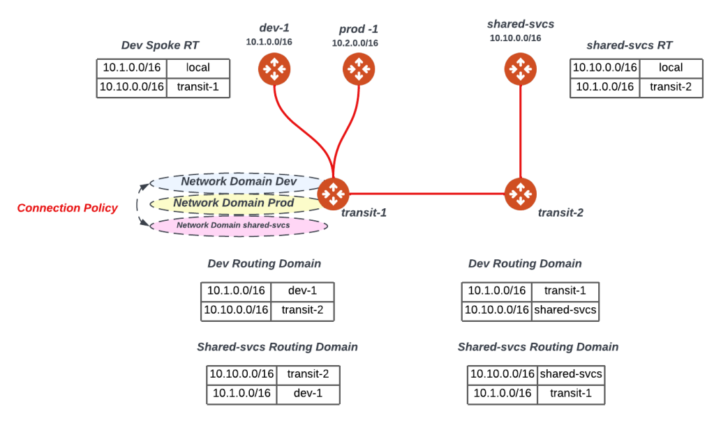
Up till the last section, we have been able to isolate dev/prod workloads across all our multi-cloud architecture. In reality, customers tend to have shared services such as NTP, DNS, Syslog, Netflow Collectors..etc that service both their production and development environments. Thus, we need to ensure that both dev/prod remain isolated but able to access shared services. A connection policy is a way to leak routes between Network Domains to allow access to shared services as depicted in the figure below. Notice that the routing tables for both dev-1 and shared-svcs spoke gateways now have the routes to each other thus allowing communications from a routing plane. The same logic can be extended to prod, thus prod/dev can’t communicate but they can communicate with shared-svcs.
Extending Segmentation to On-Premises
Now that we have extended our segmentation to all our cloud infrastructure, we would like to extend it to on-premises. In the below diagram the on-premises edge (on-prem RTR) has a Site2Cloud (S2C) connection to the transit. You can find more details about S2C here but for the purposes of our discussion, you can think of it like an IPSec tunnel with BGP running on top for route-exchange. In this setup, we would like to put the on-prem RTR’s connection to the transit in a network domain (Prod) so that it can only access the prod workloads across the different CSPs.

Extending Multiple Segments from On-Prem to Cloud
In the last section, we extended the Network Domain (prod) to on-premises. The below figure takes this a step further whereby we would like to extend all the segments from on-premises to Cloud thus enabling an end-to-end segmentation strategy. Manual VRF configuration and SDN Fabrics are both viable examples of implementing on-premises segmentation, and our goal is to extend those segments into our Multi-Cloud Network Architecture.
In the diagram the underlay RTR connection to the VGW is an IPSec tunnel but the same holds true for Direct Connect (DX). Please note the following:
On the on-premises side, I have put two routers to clarify the example, however this could be done with a single router.
Think of the underlay RTR as building connectivity between the overlay RTR and the transit.
Underlay RTR in this example is running an IPSec tunnel with BGP to AWS’s VGW thus sending all the routes including the two loopbacks that are originally advertised by the overlay RTR. Now transit-1 has reachability to Lo0 and Lo1 and overlay RTR has reachability to 10.100.0.0/16. Thus, we now have a connectivity between the overlay RTR and the transit-1.
Now that VGW has received the routes, we leverage route propagation in order to ensure these routes are advertised to transit-1 GW routing table. This is depicted in the diagram with the orange VPC router and its associated route table where all these routes are propagated. In addition, by default the transit-1 router has a default route pointing to the VPC router and thus able to reach the loopbacks advertised by the overlay router (100.100.100.1/32 & 100.100.100.2/32)

Now that we have built the underlay connectivity between the overlay RTR, and transit-1 we can now build the GRE tunnels where one tunnel is sourced from lo0 and has a destination the private IP address of the transit that belongs to 10.100.0.0/16. This tunnel interface can be configured to be in VRF/Network Domain Dev. The same logic would follow for VRF prod leveraging lo1.
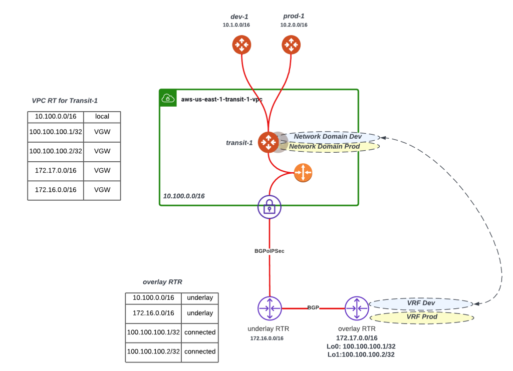
The below diagram simplifies the explanation boiling it down to:
You need an underlay connectivity (sold red line) between the overlay RTR and Transit-1
Once that connectivity is built, you can build multiple tunnels that utilize this underlay and place each of them in its own VRF/Network Domain
The below figure shows two tunnels one for Dev Network Domain/VRF extension and the other one for Prod Network Domain/VRF extension.

Segmentation Made Simple
With all its capabilities and advanced use cases, one of Aviatrix’s major values is simplicity where the controller abstracts many of the complexities within Cloud Networking. The below figure shows a network domain (Dev) being created, allowing the Dev Domain to connect to Shared-Svcs Domain and associating the Dev Domain with a spoke (aws-us-east-1-dev-1)

Check it Out
If you are keen on trying, I have created a github repository here that builds a lab infrastructure that you can use to test segmentation and other cool features and get acquainted with the platform. Sandbox Starter Tool is another great way to get acquainted with the platform. More information on this can be found here.
Subscribe to my newsletter
Read articles from Karim El Jamali directly inside your inbox. Subscribe to the newsletter, and don't miss out.
Written by

Karim El Jamali
Karim El Jamali
Self-directed and driven technology professional with 15+ years of experience in designing & implementing IP networks. I had roles in Product Management, Solutions Engineering, Technical Account Management, and Technical Enablement.