Provisioning a Highly Resilient AWS Infrastructure with Terraform: VPC, Load Balancers, and Auto Scaling Groups - Day 9
 Anandhi
Introduction
Whether it's a small webpage or a complex three-tier application, the process involves establishing a robust and dependable infrastructure in the cloud with minimal human intervention, which can be a daunting task. Terraform comes to the rescue by alleviating these challenges. This blog aims to elucidate the process of setting up a Virtual Private Cloud (VPC) environment with two availability zones, each comprising two public and private subnets. Additionally, it covers the configuration of essential components such as internet gateways, NAT gateways, Elastic IPs, security groups, Auto Scaling groups, and Application Load Balancers.

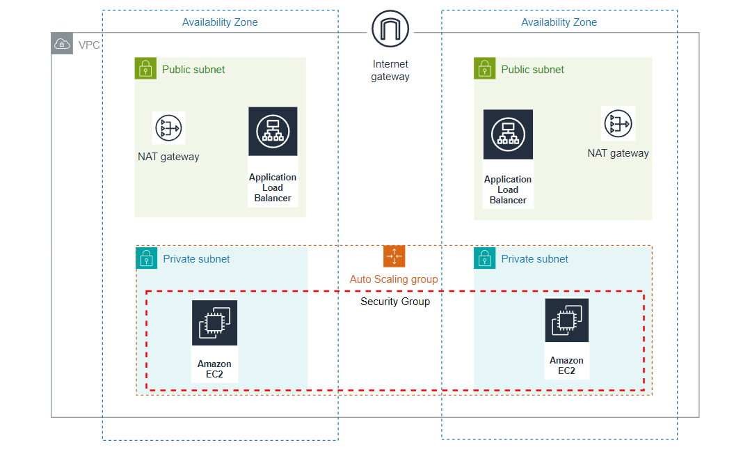
A brief overview of the project: The Virtual Private Cloud (VPC) includes both public and private subnets spread across two availability zones. To enhance resilience, each public subnet features a NAT Gateway and a Load Balancer. For added security, servers operating within the private subnets are managed via an Auto Scaling Group, ensuring their launch and termination, and they receive traffic from the Load Balancer. Connectivity to the internet for these servers is facilitated through a NAT Gateway. Users access the application via an Internet Gateway, then through the Load Balancer, ultimately reaching the application deployed in the private subnets.
Source code for Terraform Configuration files: https://github.com/Anandhi-23/Terraform_Projects
Prerequisites:
Ensure that the latest Terraform binary is installed and configured on your system.
Make sure that the AWS CLI is installed and configured with a valid AWS account possessing the necessary permissions to deploy both all the mentioned resources.
Here is the high-level overview of the AWS resources and components created by this setup.
VPC: AWS Virtual Private Cloud is commonly known as VPC which is similar to your on-premise network. It is your own isolated network in the AWS cloud associated with a specific region. Network traffic within a VPC is completely isolated from the internet and other VPCs. Using security groups and NACL you can control the traffic coming in and going outside of a VPC.
The VPC is configured in 'us-east-2' region with the CIDR block, '10.0.0.0/16'
Subnets: Subnets are segmented networks within a larger network, such as a Virtual Private Cloud (VPC) in AWS. They provide a way to organize and partition IP address space. They are associated with availability zones. There are two types of subnets. Public and Private subnet. Resources in a public subnet can be accessed directly from the internet. Whereas resources in a private subnet cannot be accessed directly from the internet.
Route Tables: In AWS, communication is carried out with the help of route tables. Route tables can be associated with VPCs and subnets. Each route table consists of a set of rules called routes. Each route or routing rule has a destination and target.
Here, three route tables have been created: one is associated with public subnets, while the other two are associated with private subnets, one for each.
Security Group: Security groups is for a specific resource (Eg: EC2 instance). It is a stateful and contains only allow rules.
The security group allows ports 22 and 80 for inbound traffic.
NAT Gateway: NAT gateway is a managed AWS service that enables instances in a private subnet to initiate outbound traffic to the internet (for software updates, license validations, etc.,) while preventing inbound traffic from reaching those instances.
To enhance resilience, each public subnet features a NAT Gateway and elastic IP is associated with each NAT Gateway.
Internet Gateway: Internet Gateway is often called 'IGW'. It is a VPC component that acts as a gateway between your VPC and the internet, enabling communication for resources in the VPC with the outside world. It plays a crucial role in providing internet connectivity to instances in your AWS environment. Instances in a public subnet can route traffic to the internet via the Internet Gateway.
Auto Scaling Group: The Auto Scaling Group manages a specified number of instances and uses the Launch Template with the required configurations to launch an instance.
Below are the Launch Template configurations for EC2 instance,
AMI ID: ami-05fb0b8c1424f266b
Instance type: t2.micro
Resource type: instance
Following are some key parameters for Auto Scaling group,
Desired capacity: 2
Maximum size: 2
Minimum size: 1
A basic static webpage is deployed on EC2 instances using user data.
Application Load Balancer: A Load Balancer is a service in AWS that distributes incoming network traffic across multiple servers (instances) to ensure no single server is overwhelmed, improving the availability and fault tolerance of applications.
Below are some key parameters for Load Balancer
Load Balancer type: Application
Target port: 80
Target protocol: HTTP
Structure of Terraform Configuration files

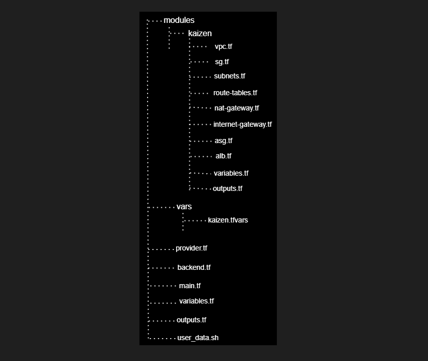
Terraform modules provide a way to organize and reuse Terraform code by encapsulating a set of resources and configurations into a modular and reusable component. This helps in organizing your infrastructure code and makes it more modular and easier to manage. Once you create a module, you can use it across different parts of your infrastructure or even in different projects. This promotes consistency and reduces duplication of code.
Here, the modules contain a subfolder named kaizen, within which all necessary resource files are placed
vars folder contains a variables file named kaizen.tfvars
The root folder comprises configuration files named provider.tf, backend.tf (for remote backend configuration), main.tf (which calls the child modules under the modules/kaizen folder), variables.tf, outputs.tf, and user_data.sh.
The child modules contain the following resources
VPC
Subnets
Route Tables
NAT Gateway
Internet Gateway
Elastic IP
Security Group
Launch Template
Auto Scaling Group
Target Group
Application Load Balancer
Listener
The application to be deployed
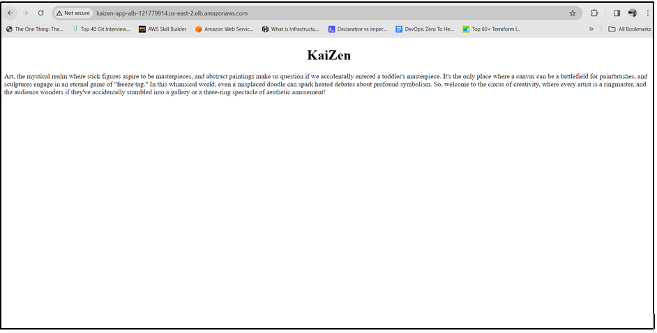
For this project, we install the Apache HTTP server on the instances created by the Auto Scaling Group and deploy a simple static webpage using user data. The application operates on port 80.
Steps for provisioning the resources
Step 1: Step up resources for remote backend
Create an S3 bucket and a DynamoDB table for remote backend and state locking configuration.
Below is the Terraform configuration for creating the S3 bucket and DynamoDB table. Alternatively, you can create them manually.
Source code: https://github.com/Anandhi-23/Terraform_Projects/blob/master/backend_configuration/remote.tf
Step 2: Create configuration for provider and remote backend
Create provider.tf and backend.tf files as depicted below for configuring the provider and backend.
provider "aws" {
  region = "us-east-2"
}
terraform {
  backend "s3" {
    bucket         = "kaizen-app-remote-backend-2024"
    key            = "app/terraform.tfstate"
    region         = "us-east-2"
    encrypt        = true
    dynamodb_table = "terraform-state-lock"
  }
}
Step 3: Set up variables
Open the kaizen.tfvars file located in the vars folder.
Adjust the variables according to your needs.
Note: Execute the upcoming commands from the root directory
Step 4: Initialize Terraform
After modifying the variables to meet your requirements, open the parent module, main.tf file, located in the root directory. This file invokes the child modules located under the modules/kaizen directory.
#calling kaizen module
module "kaizen" {
  source                   = "./modules/kaizen"
  az                       = var.az
  vpc_cidr                 = var.vpc_cidr
  vpc_enable_dns_hostnames = var.vpc_enable_dns_hostnames
  vpc_enable_dns_support   = var.vpc_enable_dns_support
  vpc_name                 = var.vpc_name
  public_subnets_cidr      = var.public_subnets_cidr
  public_ip_on_launch      = var.public_ip_on_launch
  public_subnet_name       = var.public_subnet_name
  private_subnets_cidr     = var.private_subnets_cidr
  private_subnet_name      = var.private_subnet_name
  route_table_cidr         = var.route_table_cidr
  public_route_table_name  = var.public_route_table_name
  private_route_table_name = var.private_route_table_name
  internet_gateway_name    = var.internet_gateway_name
  elastic_ip_count         = var.elastic_ip_count
  elastic_ip_name          = var.elastic_ip_name
  nat_gateway_name         = var.nat_gateway_name

  sg_name           = var.sg_name
  sg_description    = var.sg_description
  sg_cidr           = var.sg_cidr
  ingress_from_port = var.ingress_from_port
  ingress_to_port   = var.ingress_to_port
  ingress_protocol  = var.ingress_protocol
  egress_from_port  = var.egress_from_port
  egress_to_port    = var.egress_to_port
  egress_protocol   = var.egress_protocol
  sg_tag            = var.sg_tag

  alb_name                         = var.alb_name
  internal_value                   = var.internal_value
  lb_type                          = var.lb_type
  alb_tag                          = var.alb_tag
  tg_name                          = var.tg_name
  tg_port                          = var.tg_port
  tg_protocol                      = var.tg_protocol
  target_type                      = var.target_type
  health_check_path                = var.health_check_path
  health_check_port                = var.health_check_port
  health_check_protocol            = var.health_check_protocol
  health_check_healthy_threshold   = var.health_check_healthy_threshold
  health_check_unhealthy_threshold = var.health_check_unhealthy_threshold
  health_check_interval            = var.health_check_interval
  health_check_timeout             = var.health_check_timeout
  alb_listener_port                = var.alb_listener_port
  alb_listener_protocol            = var.alb_listener_protocol
  alb_listener_type                = var.alb_listener_type

  template_name        = var.template_name
  image_id             = var.image_id
  instance_type        = var.instance_type
  user_data            = var.user_data
  public_ip_address    = var.public_ip_address
  resource_type        = var.resource_type
  template_tag         = var.template_tag
  asg_desired_capacity = var.asg_desired_capacity
  asg_max_size         = var.asg_max_size
  asg_min_size         = var.asg_min_size
}
Initialize Terraform by executing the command terraform init.
This command downloads all required provider plugins and modules.
Step 5: Format and validate configurations
Execute the Terraform commands terraform fmt and terraform validate to format the configuration files for improved readability and to validate all configurations.
Step 6: Execute Terraform configuration plan
To confirm the configurations, execute terraform plan with the variable file.
terraform plan -var-file="./vars/kaizen.tfvars"
Step 7: Apply the configuration
After verification, apply the configurations using the following command. Make sure to include the variable file.
terraform apply -var-file="./vars/kaizen.tfvars" --auto-approve
Step 8: Verify the provisioned resources
After the code has been successfully executed, verify that all resources provisioned by the Terraform code are in place by visiting the AWS console.

Attempt to access the deployed application by entering the ALB DNS name in your web browser. You can retrieve the DNS from either the AWS console or from Terraform outputs.

Step 9: Destroy the configuration
To prevent unwanted billing, utilize the command below to destroy all provisioned resources.
terraform destroy -var-file="./vars/kaizen.tfvars" --auto-approve
Note: This is merely a starting point for provisioning a highly available infrastructure in the cloud using Terraform. If you intend to replicate this setup for a production environment, ensure to prioritize security and availability according to your specific requirements.
Subscribe to my newsletter
Read articles from Anandhi directly inside your inbox. Subscribe to the newsletter, and don't miss out.
Written by

Anandhi
Anandhi
DevOps enthusiast on a mission to automate, collaborate, and transform software delivery