Embedded Rust Bluetooth on ESP: BLE Scanner
 Omar Hiari
This post is a start of a new series where I'll be exploring the use of Bluetooth Low Energy along embedded Rust on the ESP32.
Introduction
Bluetooth is a wireless communication technology that enables data exchange over short distances between devices, allowing for convenient connectivity in various applications such as audio streaming, file transfer, and device synchronization. Bluetooth can take a while to wrap your head around. Other than understanding the protocol and its stack, there's more than one flavor. There's Bluetooth Classic and there's Bluetooth Low Energy or what is commonly known as BLE. Bluetooth Classic and BLE share some common components but are not compatible. This means that a BLE radio can't connect to a Bluetooth radio unless that Bluetooth radio supports BLE. This is referred to as dual mode. The focus of this post is BLE.
BLE, introduced as part of Bluetooth 4.0, extends the capabilities of traditional Bluetooth by providing energy-efficient communication for devices with low-power requirements, making it ideal for applications like wearable technology, IoT devices, and wireless sensors. BLE enables long battery life and reduced power consumption while maintaining compatibility with existing Bluetooth devices, opening up new possibilities for connected devices in diverse industries.
BLE incorporates several terms and quite an involved stack. However, to work with BLE one does not need to intimately dig into each layer, however, some terms are necessary to understand. In this post, I'll try to simplify some of these concepts and explain the necessary terms. In this code, I'm going to demonstrate how to perform a scan using the ESP as a central device. What these terms mean will be explained in more detail soon.
The code will be built using the esp32-nimble crate. The esp32-nimble crate is a wrapper for the ESP32 NimBLE Bluetooth stack. The crate is inspired by the NimBLE-Arduino project. NimBLE is an open source BLE stack fully compliant with the Bluetooth specification providing both host and controller functionalities. NimBLE is also part of the Apache MyNewt project. The ESP-IDF supports only a port of the NimBLE host stack and provides a different controller implementation.
📚 Knowledge Pre-requisites
To understand the content of this post, you need the following:
Basic knowledge of coding in Rust.
Familiarity with standard library development in Rust with the ESP.
Basic knowledge of networking layering concepts/stacks (ex. OSI model).
Basic knowledge of Bluetooth.
💾 Software Setup
All the code presented in this post is available on the apollolabs ESP32C3 git repo. Note that if the code on the git repo is slightly different then it means that it was modified to enhance the code quality or accommodate any HAL/Rust updates.
🛠 Hardware Setup
Materials
-
🔌 Connections
No connections are required for this example.
👨🎨 Software Design
Its always confused me how Bluetooth seems to have two parallel stacks and several roles. Though looking at the stack and roles from device connection state would help simplify understanding. In that context, lets consider two main states; pre-connection and post-connection. Let's keep that in mind as we inspect the layers and device roles.
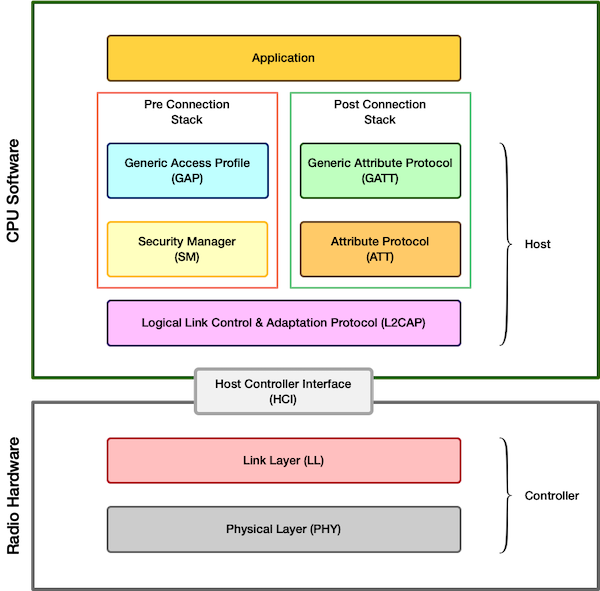
The figure below shows the BLE stack. Note how there is a host part and controller part. The controller layers lie in the hardware and handle the low level physical aspects of communication, such as radio frequencies, modulation, packet encoding, packet transmission, and packet reception. The host layers lie in the software and are responsible for higher-level protocol handling, including connection management, security, and data processing. The host and the controller interact with each other through an interface often referred to as the host controller interface of (HCI). This can be simply a serial interface like UART. You can potentially think of the controller and the host as two different ICs that exchange data with each other.
There are parallels to be drawn from computer network systems to help understand. You've probably seen network interface controllers (NICs), or network cards. Some NICs for example would enable connecting to an ethernet network or WiFi from one end and a computer mother board from another end. The motherboard connection could be something like a PCI interface. This is equivalent to the HCI in BLE context.
The BLE protocol stack is composed of several layers, each serving distinct functions in facilitating communication between BLE-enabled devices. These layers include:
Physical Layer (PHY): This layer of is responsible for converting digital data into radio waves and vice versa for transmission.
Link Layer (LL): This layer among several tasks, manages the connection establishment, data packet format, and error handling.
Host Controller Interface (HCI): The HCI layer provides an interface between the Host and the Controller. It standardizes communication between the Host (typically a microprocessor running higher-level protocols) and the Controller (responsible for low-level radio operations).
Logical Link Control and Adaptation Protocol (L2CAP): L2CAP is a protocol layer that provides segmentation and reassembly of data packets, multiplexing of multiple logical connections, and quality of service (QoS) negotiation.
Security Manager (SM): This layer is responsible for establishing and managing security features in BLE connections.
Attribute Profile (ATT) and Generic Attribute Profile (GATT): These layers define a hierarchical data structure used to organize data exchanged between BLE devices. They enables devices to expose services, characteristics, and descriptors, allowing for standardized communication and interoperability.
Generic Access Profile (GAP): This layer is responsible for managing the basic aspects of device interaction in a BLE network. Things like discovery, advertising, and connection establishment.
Note how in the figure, the layers on the left hand side are pre connection layers (SM and GAP). This is because the tasks they perform are pre connection tasks; advertising, authenticating, discovery...etc.. The right hand side, on the other hand, includes the post connection layers (ATT and GATT) performing post connection tasks mainly to do with data exchange.
🤹♂️ Device Roles
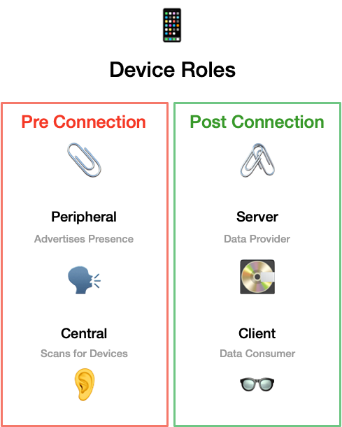
There are four main terms that float around with device roles in BLE; Central, Peripheral, Server, and Client. Just like the stack layers, we can look at the roles from a pre/post connection perspective.
Pre Connection Roles:
Central: The "central" is a device that typically initiates connections and requests data or services from peripheral devices. Central devices can scan for nearby peripherals, establish connections, and exchange data with them.
Peripheral: The "peripheral" is a device that advertises its presence and provides services to central devices.
Post Connection Roles :
Client: The "client" is a device that consumes data or services provided by a "server."
Server: The "server" is a device that provides data or services to clients.
In this post, we are going to program the ESP as a central device scanning for other devices. When scanning there are several scan settings available and depend on what the application desires. Factors considered include device discovery frequency, power consumption, and connection reliability. In this post we're not going to use them all, but its beneficial to know what is available. Key settings include the following:
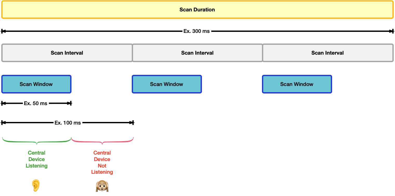
Scan Interval: As shown in the figure below, the scan interval determines the time interval between successive scans performed by the BLE device. It affects how frequently the device scans for nearby devices. Shorter scan intervals result in more frequent scanning but may consume more power. A good practice is to set a relatively short scan interval, so that the scanning process is more likely to receive the advertising packets. The scanning interval can go up to seconds but is typically specified in milliseconds.
Scan Window: The scan window specifies the duration within each scan interval during which the device actively listens for advertising packets. It affects the duration of each scanning cycle and impacts the likelihood of discovering nearby devices. Adjusting the scan window allows balancing between power consumption and device discovery frequency.
Scan Duration: The scan duration determines the total duration of a single scanning cycle, including both the scanning interval and scan window. It affects how long the device spends actively scanning for nearby devices before entering an idle state. Longer scan durations increase the likelihood of discovering nearby devices but may consume more power.
Scan Type: The scan type specifies whether the scanning process is passive or active. In passive scanning, the device only listens for advertising packets from nearby devices. In active scanning, the device sends out scan requests to nearby devices, prompting them to respond with advertising packets.
Filter Policies: Filter policies define which advertising packets the device filters or ignores during the scanning process. They can filter devices based on specific criteria such as device address, advertising data, or signal strength. Filter policies help optimize the scanning process by focusing on relevant advertising packets.
Understanding the above terms would make our job quite straight forward using the esp32-nimble crate.
👨💻 Code Implementation
📥 Crate Imports
In this implementation, the following crates are required:
The
esp_idf_halcrate to import thetask::block_onfunction.The
esp_idf_syscrate since its needed.The
esp32_nimblecrate for the BLE abstractions.
use esp32_nimble::BLEDevice;
use esp_idf_hal::task::block_on;
use esp_idf_sys as _;
🎛 Initialization/Configuration Code
1️⃣ Obtain a handle for the BLE device: Similar to the pattern we've seen in embedded Rust with peripherals, as part of the singleton design pattern, we first have to take ownership of the device peripherals. In this context, its the BLEDevice that we need to take ownership of. You might have guessed it already, this is done using the take() associated method. Here I create a BLE device handler named ble_device as follows:
let ble_device = BLEDevice::take();
Although not obvious, note that take not only provides ownership, but behind the scenes also initializes the NimBLE stack.
2️⃣ Create a Scan Instance: After initializing the NimBLE stack we create a scan instance by calling get_scan, this will create a BLEScan instance. This instance would allow us to start looking for advertising servers. Heres the code:
let ble_scan = ble_device.get_scan();
3️⃣ Configure Scan Parameters and Callback: Now that we have a scan instance we can configure the scan parameters discussed earlier; scan type, interval, and window. Additionally, we need to configure the behaviour on the return of a scan result. These parameters can all be configured by calling BLEScan methods on the ble_scan instance we created.
To set the scan type, there exists the active_scan method that takes a single bool type argument. To set the interval there exists the interval method that takes a single u32 type argument representing the interval in ms. To set the window there exists the window method that takes a single u32 type argument representing the window in ms.
Finally, whenever our central device detects an advertising device, the behaviour needs to be identified. This is done using the on_result method. The on_result parameter is a callback that is called when a new scan result is detected. The first parameter is a reference to ble_scan instance itself, and the second is a reference to a detected device of BLEAdvertisedDevice type. BLEAdvertisedDevice contains alot of data about the advertiser device obtained by various methods. At a minimum, we're going to retrieve the name, address and rssi of a advertising device. This is demonstrated in the following code:
ble_scan
    .active_scan(true)
    .interval(100)
    .window(50)
    .on_result(|_scan, param| {
        println!(
            "Advertised Device Name: {:?}, Address: {:?} dB, RSSI: {:?}",
            param.name(),
            param.addr(),
            param.rssi()
        );
    });
Note that the scan interval chosen is 100ms and the scan window is 50ms.
That's it for configuration!
📱 Application Code
Start the Scan: All we have to do now is start the scan process. This is done by calling the BLEScan start method. start takes one parameter which specifies a scan duration in milliseconds. Note though how start is an async function that returns a Future. This means that it would defer execution until the scan is completed. For that, note in the full application how the code is wrapped in a async block inside a block_on function. This serves to block execution until the scan process is completed.
ble_scan.start(5000).await.unwrap();
println!("Scan finished");
📱Full Application Code
Here is the full code for the implementation described in this post. You can additionally find the full project and others available on the apollolabs ESP32C3 git repo.
use esp32_nimble::BLEDevice;
use esp_idf_hal::task::block_on;
use esp_idf_sys as _;

fn main() {
    esp_idf_svc::sys::link_patches();

    block_on(async {
        let ble_device = BLEDevice::take();
        let ble_scan = ble_device.get_scan();
        ble_scan
            .active_scan(true)
            .interval(100)
            .window(50)
            .on_result(|_scan, param| {
                println!(
                    "Advertised Device Name: {:?}, Address: {:?} dB, RSSI: {:?}",
                    param.name(),
                    param.addr(),
                    param.rssi()
                );
            });
        ble_scan.start(5000).await.unwrap();
        println!("Scan finished");
    });
}
Conclusion
This post introduced how to start working with BLE on the ESP32-C3 with Rust. This was by using the esp32-nimble crate in a standard library development environment using the esp-idf-hal . In this post, the ESP32-C3 was configured as a central device to perform a scan for advertising BLE devices. Have any questions? Share your thoughts in the comments below 👇.
Subscribe to my newsletter
Read articles from Omar Hiari directly inside your inbox. Subscribe to the newsletter, and don't miss out.
Written by

Omar Hiari
Omar Hiari
I am an 📟 Embedded Engineer with years of experience in both industry 🏭 and academia 🏫. Passionate Mentor 👨💼 and Instructor 👨🏫. Aspiring Rustacean 🦀