React JS + TS: A good-looking, parametrizable JSX representation of a rectilinear route, without using HTML 5 Canvas
 Emzar Panikashvili
cover image uses: Image by brgfx on Freepik , Image by brgfx on Freepik , Image by catalyststuff on Freepik , Image by logturnal on Freepik
GitHub: https://github.com/epanikas/cell-route-drawing/tree/feature/blog-post-branch
In one of my projects I faced a problem, when blocks, represented by standard HTML means, such as div's and span's, created by React JSX elements, should have been connected by rectilinear routes, forming a kind of visual graph representation, when nodes were HTML components, and edges were rectilinear lines, connecting them.
One can easily imagine such kind of situation, when working on graphs related to relationship representation, such as organigrams or social link maps.
We have HTML 5 Canvas, so why not use it?
HTML 5 Canvas is a great option for anything related to graphical representation on HTML pages. However, I wasn't sure how well it could be used with standard HTML blocks, which were necessary to represent the nodes of the graph.
The graph nodes were supposed to be drawn by React JS JSX elements, ultimately ending up on the page as standard HTML blocks, such as div's and span's. The pre-designed UI libraries, such as Material UI, particularly looked attractive for graph node representation.
These pre-designed blocks, however, don't exist for HTML 5 Canvas (or at least currently I'm not aware of such libraries). So it was quite important to stick with pure HTML (generated by React JS, as pointed out before). In addition, currently, I'm not aware of HTML 5 Canvas components that would support CSS styling.
These considerations - JSX elements, rich UI libraries, and CSS styling - pre-conditioned my choice of using standard HTML blocks instead of graphical HTML 5 Canvas widgets.
The workbench setup
The main idea of the graph visual representation using React JSX was to use fixed predefined positioning of each graph node, achieved thanks to the CSS attribute "position" set to "absolute".
This way each graph node wouldn't depend on dynamically positioned elements on the page, maintaining its pre-calculated position. The static positioning of the graph nodes is important so that the routes, connecting the nodes, would also be pre-calculated.
For clarity, we will be positioning graph nodes and drawing routes on a grid with a predefined cell size.
We will be using a standard Typescript + React JS setup.
Data structure
The following classes would constitute the data structure:
BoxSize - the size of the grid cell
export class BoxSize {
    readonly sizeX: number;
    readonly sizeY: number;
    ...
}
LayoutPosition - the (x, y) positioning in grid coordinates
export class LayoutPosition {
    readonly x: number;
    readonly y: number;
    ...
    public toCanvasPosition(cellSize: BoxSize, shift: CanvasPosition): CanvasPosition {
        return new CanvasPosition(
            shift.x + this.x * cellSize.sizeX,
            shift.y + this.y * cellSize.sizeY
        );
    }
}
CanvasPosition - the (x, y) positioning in absolute page coordinates (so forth called canvas coordinates)
export class CanvasPosition {
  readonly x: number;
  readonly y: number;
    ...
}
CellRoute - a collection of points, representing a route in grid coordinates. Each pair of points should represent either a vertical or horizontal route segment (recall that a route is rectilinear)
export class CellRoute {
  readonly cells: LayoutPosition[] = [];
    ...
}
CellRouteSegment - two points in grid coordinates, representing one segment of a route, either vertical or horizontal
export class CellRouteSegment {
  private readonly p1: LayoutPosition;
  private readonly p2: LayoutPosition;
  private readonly vertical: boolean;
    ...
}
CanvasRectangle - a bounding rectangle, represented by two points, in canvas coordinates
export class CanvasRectangle {
    p1: CanvasPosition;
    p2: CanvasPosition;

    constructor(p1: CanvasPosition, p2: CanvasPosition) {
        this.p1 = p1;
        this.p2 = p2;
    }

    toStyle(): CSSProperties {
        return CssPropertiesUtils.absolutePositioning(this.p1, this.p2);
    }
}
Note the method CssPropertiesUtils.absolutePositioning, which generates the CSS style of a rectangle with position "absolute", similar to this:
position: absolute;
top: 140px;
left: 630px;
width: 20px;
height: 220px;
Visual components
The main visual components would include:
RouteWire - given a route, as an argument of type CellRoute, draws the route
export class RouteProps {
    route: CellRoute;
    cellSize: BoxSize;
    color: string;
    lineWidth: number;
    radius: number;
    borderWidth: number;
    ...
}

export class RouteWire extends React.Component<RouteProps> {

    public override render(): JSX.Element {
        const { route, color, cellSize, lineWidth, radius, borderWidth} = this.props;

        const routeId = "route-";

        const segments: CellRouteSegment[] = route!.getRouteSegments();
        const drawnSegments: JSX.Element[] = [];
        for (var i: number = 0; i < segments.length; ++i) {

            const rs: CellRouteSegment = segments[i];
            const key = routeId + i + "-segment";

            drawnSegments.push(<RouteWireSegment key={key}
                                           routeId={routeId}
                                           cellSize={cellSize}
                                           routeSegment={rs}
                                           color={color}
                                           lineWidth={lineWidth}
                                           borderWidth={borderWidth}
                                           radius={radius}
            />);
        }

        return <div key={routeId}>{drawnSegments}</div>
    }
}
RouteWireSegment - an actual building block of route visual representation, responsible for drawing a single route segment, horizontal or vertical
export class RouteWireSegmentProps {
    routeId: string
    cellSize: BoxSize;
    routeSegment: CellRouteSegment;
    lineWidth: number = 5;
    borderWidth: number = 2;
    radius: number = 10;
    color: string = "red";
    ...
}

export class RouteWireSegment extends React.Component<RouteWireSegmentProps> {

    public override render(): JSX.Element {
        const {routeId, routeSegment, borderWidth, color} = this.props;

        const key: string = routeId + routeSegment.getP1() + routeSegment.getP2();

        const segmentRectangle: CanvasRectangle = this.calculateRouteCanvasRectangle();

        const border: CSSProperties = {} as CSSProperties;
        // definition of the route segment rectangle border
        return <div
            key={key + "-main"}
            style={CssPropertiesUtils.mergeCssProperties(segmentRectangle.toStyle(), border)} />;
    }

    private calculateRouteCanvasRectangle(): CanvasRectangle {

        const { routeSegment, cellSize } = this.props;

        const topLeftCanvas: CanvasPosition = routeSegment.topLeft().toCanvasPosition(cellSize);
        const bottomRightCanvas: CanvasPosition = routeSegment.bottomRight().toCanvasPosition(cellSize);

        if (routeSegment.isVertical()) {
            return this.calculateCanvasRectangleForVertical(topLeftCanvas, bottomRightCanvas);
        } else {
            return this.calculateCanvasRectangleForHorizontal(topLeftCanvas, bottomRightCanvas);
        }

    }

    private calculateCanvasRectangleForVertical(topLeftCanvas: CanvasPosition,
                                                bottomRightCanvas: CanvasPosition): CanvasRectangle {

        const { lineWidth, radius, borderWidth} = this.props;
        const halfLineWidth = lineWidth / 2;

        return  new CanvasRectangle(
            new CanvasPosition(topLeftCanvas.x - halfLineWidth - borderWidth, topLeftCanvas.y - halfLineWidth),
            new CanvasPosition(bottomRightCanvas.x + halfLineWidth - borderWidth, bottomRightCanvas.y + halfLineWidth)
        );
    }

    private calculateCanvasRectangleForHorizontal(topLeftCanvas: CanvasPosition,
                                                  bottomRightCanvas: CanvasPosition): CanvasRectangle {

        const { lineWidth, radius, borderWidth} = this.props;
        const halfLineWidth = lineWidth / 2;

        return new CanvasRectangle(
            new CanvasPosition(topLeftCanvas.x - halfLineWidth, topLeftCanvas.y - halfLineWidth - borderWidth),
            new CanvasPosition(bottomRightCanvas.x + halfLineWidth, bottomRightCanvas.y + halfLineWidth - borderWidth)
        );
    }

}
Let's have a closer look at the line, actually generating a div, which would represent a route segment:
<div key={key + "-main"}
     style={CssPropertiesUtils.mergeCssProperties(segmentRectangle.toStyle(), border)} />
As one can see, a route segment div is positioned thanks to the absolute positioning, generated by the method CanvasRectangle.toStyle(), described earlier. The CSS style, generated by this method, is merged with another CSS style, representing the border of the route segment, defined in the variable border in the following manner:
const border: CSSProperties = {} as CSSProperties;
border.borderTopWidth = routeSegment.isVertical() ? "0" : borderWidth + "px";
border.borderBottomWidth = routeSegment.isVertical() ? "0" : borderWidth + "px";
border.borderLeftWidth = routeSegment.isVertical() ? borderWidth + "px" : "0";
border.borderRightWidth = routeSegment.isVertical() ? borderWidth + "px" : "0";
border.color = color;
border.borderTopStyle = routeSegment.isVertical() ? "none" : "solid";
border.borderBottomStyle = routeSegment.isVertical() ? "none" : "solid";
border.borderLeftStyle = routeSegment.isVertical() ? "solid" : "none";
border.borderRightStyle = routeSegment.isVertical() ? "solid" : "none";
The final CSS style of the drawn route segment looks like this:
    position: absolute;
    top: 140px;
    left: 630px;
    width: 20px;
    height: 220px;
    border-width: 0px 10px;
    color: rgba(114, 217, 96, 0.5);
    border-style: none solid;
    border-top-style: none;
    border-right-style: solid;
    border-bottom-style: none;
    border-left-style: solid;
Route style parametrization
As one might have already noticed, the properties of the RouteWireSegment component include a set of attributes, related to the route styling:
lineWidth: the thickness of a drawn route, i.e. the distance between two opposite borders of the route segment
borderWidth: the width of the outer border of the route
radius: the rounding radius for route corners, read on to see its implementation
color: the color of the route, given as a string in any format, compatible with CSS color representation
The implementation code of the route visual components - RouteWire and RouteWireSegment, presented so far - uses all these parameters, except for radius. Here is the intermediary result:
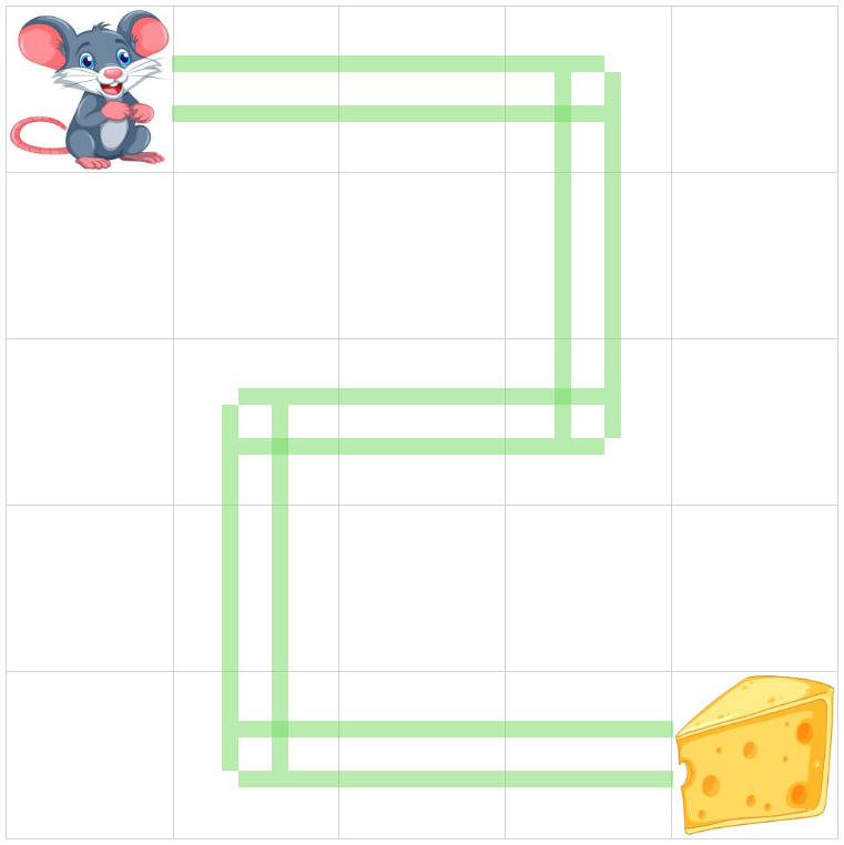
Digging deeper
So far the presented intermediate result doesn't look very convincing. Indeed, the lines of segments are crossing each other, and the overall impression is far from being accomplished.
We need to work harder in particular on route corners.
Making a place for rounded corners
First of all, let's make sure that the route segments are not crossing each other. The positioning and width / height of route segments should be calculated such that the corners would be left empty so that they could be filled in by special sections - round corners.
To achieve this let's add two additional parameters to the RouteWireSegment component - the next segment and the previous segment - as follows:
export class RouteWireSegmentProps {
    ...
    prevSegment?: CellRouteSegment;
    nextSegment?: CellRouteSegment;
}
This information is required to determine, whether a route should leave a space for rounded corners on its ends or not.
The algorithm is rather simple, and can be summarized as follows:
given a route segment AB
denote by topLeftAdjacent a segment among prevSegment and nextSegment, that is adjacent to the route segment's top-left corner
denote by bottomRightAdjacent a segment among prevSegment and nextSegment, that is adjacent to the route segment's bottom-right corner
if the topLeftAdjacent segment is present, cut the distance L = radius + lineWidth + 2 \ borderWidth from the top-left* corner of the segment
if the bottomRightAdjacent segment is present, cut the distance L = radius + lineWidth + 2 \ borderWidth from the bottom-right* corner of the segment
It is straightforward to see why the distance to cut out is calculated as the sum of radius, lineWidth, and twice the borderWidth:
radius will be taken by the inner rounded corner
lineWidth is the width of the adjacent route segment, with which this segment shouldn't overlap
and the borderWidth should be added twice as there are two borders on the route segment.
Here is the implementation of this calculation for a vertical segment (it is similar to a horizontal one):
    private calculateCanvasRectangleForVertical(topLeftCanvas: CanvasPosition,
                                                bottomRightCanvas: CanvasPosition,
                                                hasTopLeftAdjacent: boolean,
                                                hasBottomRightAdjacent: boolean): CanvasRectangle {

        const {lineWidth, radius, borderWidth} = this.props;
        const halfLineWidth = lineWidth / 2;

        let mainTopLeft: CanvasPosition = new CanvasPosition(topLeftCanvas.x - halfLineWidth - borderWidth, topLeftCanvas.y - halfLineWidth);
        let mainBottomRight: CanvasPosition = new CanvasPosition(bottomRightCanvas.x + halfLineWidth - borderWidth, bottomRightCanvas.y + halfLineWidth);

        if (hasTopLeftAdjacent) {
            // cut out L from the top-left segment corner
            mainTopLeft = new CanvasPosition(
                                mainTopLeft.x,
                                mainTopLeft.y + radius + lineWidth + 2 * borderWidth);
        }

        if (hasBottomRightAdjacent) {
            // cut out L from the bottom-right segment corner
            mainBottomRight = new CanvasPosition(
                                mainBottomRight.x,
                                mainBottomRight.y - radius - lineWidth - 2 * borderWidth);
        }

        return new CanvasRectangle(mainTopLeft, mainBottomRight);
    }
Here is the result of this modification:
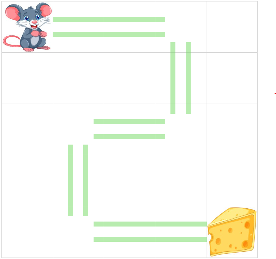
Positioning the rounded corners
The main idea behind drawing the rounded corners is to have two squares - inner and outer. The CSS attribute border-radius allows one to specify the radius of the rounded corner of the square. A full circle circumference will be drawn when this radius is set to 100%. Our goal is to take only a quarter of this circumference, which would form a necessary portion of the rounded corner between segments.
By convention we assume that each segment will be responsible for drawing a rounded corner between itself and the previous segment (if present).
To position correctly the inner and outer squares that would format a rounded corner, first we need to determine the type of the rounded corner that is being drawn. Indeed, it is easy to see that there are only four possible positions for a rounded corner:
| type | xDirection | yDirection |
| top-left | 1 | 1 |
| top-right | -1 | 1 |
| bottom-left | 1 | -1 |
| bottom-right | -1 | -1 |
Note that each corner type also unambiguously determines the x/y directions for the rounded corner square, i.e. the direction in which each dimension should grow to form the correctly positioned square.
The dimensions of the inner and outer squares are easy to calculate:
let inner square side Di = radius + borderWidth
let outer square side Do = radius + lineWidth + 2 \ borderWidth*
It's obvious as well that the inner corner point of the inner and outer squares is the same, and can be calculated from the common point between this segment and the adjacent one:
let P(x, y) be the common point between this segment and the adjacent one
let CT(xDirection, yDirection) be the corner type of the corner, along with the corresponding xDirection and yDirection (see the table above)
let D = lineWidth / 2 + radius + borderWidth
then the common inner point C(x, y) of the inner and outer squares can be calculated as follows:
C.x = P.x + CT.xDirection * D
C.y = P.y + CT.yDirection * D
Each rectangle, including inner and outer squares, can be determined by two opposite points - top-left and bottom-right or top-right and bottom-left. In other words, any two points would form a rectangle.
This method of rectangle definition would presume that inner and outer rounded corner squares can also be determined by two points only. Moreover, the first point of these two points is already found - this is the common inner corner point calculated earlier.
Hence the only thing that is left to do to determine the inner and outer rectangles is to find out the second defining point for each one of them.
let C(x, y) be the common inner corner point, calculated as has been shown above
let I(x, y) be the second point for inner square and O(x, y) be the second point for outer square
let:
I.x = C.x - CT.xDirection * Di
I.y = C.y - CT.yDirection * Di
and
O.x = C.x - CT.xDirection * Do
O.y = C.y - CT.yDirection * Do
then
the inner square will be defined as Rectangle(C(x, y), I(x, y))
the outer square will be defined as Rectangle(C(x, y), O(x, y))
Let's have a look at the result of the calculations presented above:
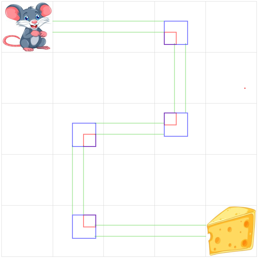
In this illustration, the red square represents the inner square, while the blue - the outer one. One can see the common inner common point, mentioned above - this is the common point between inner and outer squares.
We can also notice the misalignment occurring in some cases between the edges of the inner and outer square and the edges of the route segment. These visual artifacts will be dealt with later.
Rounded corner edges
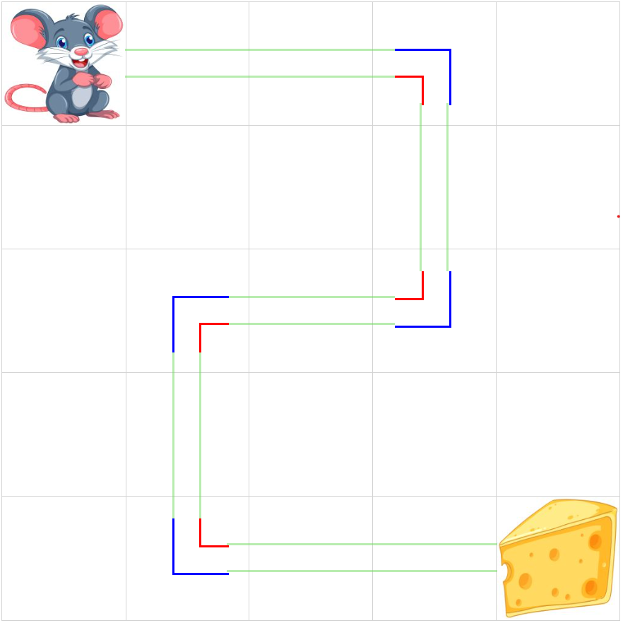
So far we have positioned the inner and outer squares. Now it's time to draw only a portion of them - in particular two edges that would form a corner.
To achieve the desired result we will be using the CSS attribute border-style, where we will be specifying a style separately for each edge of the square - top, right, bottom and left.
The pattern that should be used is also determined by the type of the corner - top-left, bottom-right, etc.
Here is the code of the corresponding method:
    getBorderStyle(cornerType: CornerType): import("csstype").Property.BorderStyle {

        switch (cornerType) {
            case CornerType.topLeft:
                return "solid none none solid";
            case CornerType.topRight:
                return "solid solid none none";
            case CornerType.bottomLeft:
                return "none none solid solid";
            case CornerType.bottomRight:
                return "none solid solid none";
        }
    }
The result of this modification is as follows:
Rounding the corners
Finally, we are ready to draw the rounded corners as .. well, as rounded!
Again, thanks to the rich CSS vocabulary we can specify separately the radius of each corner of the square: top-left, top-right etc.
Here is the corresponding method:
    private getBorderRadius(cornerType: CornerType): import("csstype").Property.BorderRadius {

        switch (cornerType) {
            case CornerType.topLeft:
                return "100% 0 0 0";
            case CornerType.topRight:
                return "0 100% 0 0";
            case CornerType.bottomLeft:
                return "0 0 0 100%";
            case CornerType.bottomRight:
                return "0 0 100% 0";
        }
    }
Here is the result of this modification:
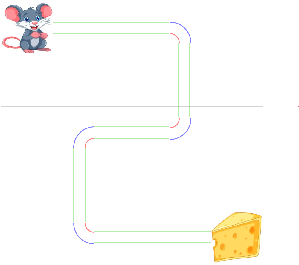
Addressing the misalignment artifact
As has been announced earlier, the annoying misalignment artifact between the rounded corners and the edges will be dealt with later. Well, the time has come!
To see the root cause of this misalignment we'll need to have a closer look at the inner and outer squares, and in particular at the CSS box model:

What is important here for us is the fact that the border width is not included in the dimensions of the box.
However, in our case, the square definition is done as follows:
first, two opposite points of the square are specified - P1(x, y) and P2(x, y)
second, the square absolute positioning is calculated, as well as the width and height of the rectangle, all that from the two points P1 and P2
finally, the rectangle is drawn based on the values for top, left, width, and height CSS attributes calculated above, and, in addition, its border is specified, according to the argument borderWidth
This algorithm doesn't work well in all the cases. It only works for the top-left corner. For all other corner types, this algorithm results in misalignment artifacts.
To fix this misalignment we have two options:
Option 1: change the calculation of the common inner corner point as follows:
C.x = P.x + (CT.xDirection < 0 ? -(D + borderWidth) : D)
C.y = P.y + CT.yDirection < 0 ? -(D + borderWidth) : D)
Option 2: use the CSS attribute box-sizing set to border-box for inner and outer squares
The following image demonstrates the fix based on Option 1 (Option 2 gives a similar result):
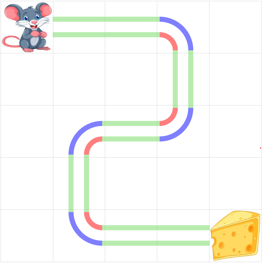
Conclusion
In this article, we have discussed a possible solution to a problem, when a rectilinear route should be drawn on a HTML page, without using graphical elements, such as HTML 5 Canvas.
We have discussed an approach based on the absolute positioning of the route elements - segments.
We have also demonstrated a solution to the problem of drawing the route segment with rounded corners. This task, simple and trivial at first sight, turned out to be quite tricky.
Finally, we have suggested a solution to the rounded corners misalignment problem.
The working code, illustrating this article, can be found on the following GitHub repository: https://github.com/epanikas/cell-route-drawing/tree/feature/blog-post-branch
Subscribe to my newsletter
Read articles from Emzar Panikashvili directly inside your inbox. Subscribe to the newsletter, and don't miss out.
Written by
