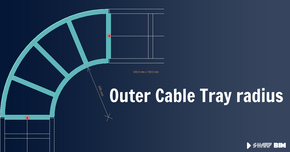
Outer CableTray radius
 Moustafa Khalil
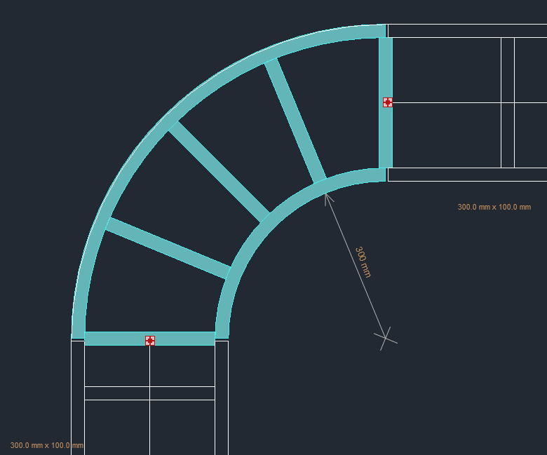
MEP fittings in Revit are families designed for MEP projects. Since these families can come in various forms, tracking values like the bend radius between two connectors can be challenging.

One approach is to add a reporting parameter for the outer radius within the family, which can then be used for scheduling. However, manually adding this report to each family can be time-consuming.
Another possible method involves coding, which, although not straightforward, can be applied to all families once implemented.
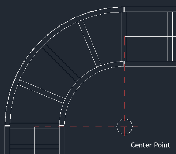
To start, we need to identify the two connectors for which we want to determine the outer radius. From these 2 connectors we extract the origin points. The points are crucial for finding the center point of the arc. Getting the center point can be reached by drawing a perpendicular line to the cable tray curve direction and projecting the second point onto this line, by which we can locate the center.

Next, draw an arc connecting the two points with the radius. The radius can be measured by getting the distance between any of the connectors to the center point we evaluated. This approach will establish the centerline connection between the two MEP curves. Finally, by using the CreateOffsetfunction with a distance equal to half the cable tray width, we can achieve our desired outcome.
Below is a sample code that summarizes the process. You need to pay attention to the angles required to draw the arc. The start angle must be less than the end angle. One common observation in most MEP Fittings, especially the elbow type, is that the path used to sweep the profile consists of two lines and one arc. These two lines provide a smooth connection when used. Therefore, you also need to consider this aspect to obtain an accurate result.
Let us know your findings.
// assuming you already have the two connectors.
// we get the curves lines from its owner.
var horizontalLine = ((LocationCurve)connectorA.Owner.Location).Curve as Line;
var verticalLine = ((LocationCurve)connectorB.Owner.Location).Curve as Line;

// catch the distance and location of the 2 connectors and the distance between
var originA = connectorA.Origin;
var originB = connectorB.Origin;
var diagonalDistance = originA.DistanceTo(originB) * 2;

// get the sketchplan used to draw such cable trays
var sketchPlan = SketchPlane.Create(Doc, ((MEPCurve)connectorA.Owner).ReferenceLevel.Id).GetPlane();

// now we need draw a perpendicular line to any of the mep curves.
var perDirection = horizontalLine.Direction.CrossProduct(sketchPlan.Normal);
var perpL1 = Line.CreateBound(originA - perDirection * diagonalDistance, originA + perDirection * diagonalDistance);

var perDirection2 = verticalLine.Direction.CrossProduct(sketchPlan.Normal);
var perpL2 = Line.CreateBound(originB - perDirection2 * diagonalDistance, originB + perDirection2 * diagonalDistance);

// then project the second point over this perpendicular curve to get the center point
perpL2.Intersect(perpL1, out IntersectionResultArray inters);
//perpL1.Project(originB).XYZPoint;
var centerPoint = inters.get_Item(0).XYZPoint;

// arc requires 2 angles start and end
double angleX = sketchPlan.XVec.AngleTo((originA - centerPoint).Normalize());
double angleY = sketchPlan.XVec.AngleTo((originB - centerPoint).Normalize());

if (angleX > angleY)
{
    (angleX,angleY) = (angleY,angleX);
}
// draw the arc <= this is in the zero position "sketchplan origin point"
Curve arc = Arc.Create(sketchPlan, originB.DistanceTo(centerPoint), angleX, angleY);

// move the arc to the center point
arc = arc.CreateTransformed(Transform.CreateTranslation(centerPoint));

// create the offset needed to get the outer Radius
arc = arc.CreateOffset(((MEPCurve)connectorA.Owner).Width / 2, sketchPlan.Normal);
Subscribe to my newsletter
Read articles from Moustafa Khalil directly inside your inbox. Subscribe to the newsletter, and don't miss out.
Written by

Moustafa Khalil
Moustafa Khalil
I'm Moustafa Khalil El-Sayed, an Egyptian native with a passion for architecture and technology. After completing high school in 1999, I embarked on my journey into architecture, earning my Bachelor's degree in Architecture in 2004. My academic pursuits continued, and I later acquired my Master's degree in Architecture from Wings University. However, my thirst for knowledge extended beyond architectural design, leading me to pursue a degree in Computer Science as well. Driven by a desire to innovate, I began self-teaching computer science, which later empowered me to achieve my Associate degree in Computer Science from the University of the People more easily. Armed with dual expertise in architecture and computer science, I've cultivated a unique skill set that blends creativity with technical acumen. My career has taken me across borders, from Egypt to Oman and the UAE, where I've honed my skills as an architect. As a graduate architect and a proficient .NET BIM Solution Developer, I specialize in translating unique visions into tangible realities. My role extends beyond conventional architectural practices; I leverage technology to streamline processes and enhance project outcomes. My journey into programming began with developing script-based Excel tools to augment project management efforts, notably during the Sharm El Sheikh development. Over time, I expanded my programming prowess to address practical challenges encountered in bridging Revit and AutoCAD within my professional sphere. Several of my applications, born from this evolution, have gained recognition, with some even being featured on the Autodesk website. I am committed to pushing boundaries and continually enriching the intersection of architecture and technology, ensuring that my clients benefit from cutting-edge solutions tailored to their needs.