The System Design of My Football (Soccer) Prediction App
 SK
SK
The aim of a system design is to create a blueprint, or a high-level view, for building a particular system according to specification. This article carries on from the previous one entitled “Planning My Football (Soccer) Prediction App”.
In the previous article, we looked at the plan for delivering the artifacts, including code, that lead to the actual building of the system. In that article, I promised several documents, which I will summarise and present as future articles on my blog, that will contain the system design, the UI/UX design, and the software design or architecture.
Without further ado, let’s jump right into it.
Software Requirements
Every good system design starts with good requirements gathering. However this is meant to be an adequate system, so the requirements will also have to be adequate. I have used the convention of dividing them into three: use cases, functional and non-functional requirements. Previously I had said that I don’t have the know-how of putting together the non-functional requirements but here I will come up with brief descriptions of them and not get too complicated.
Use Cases
The web application that we are trying to deliver is a football app that looks at historical data for a starting lineup of a team and from there tries to predict the outcome of the upcoming match against a starting lineup of another team.
Use Case:
Title: Lineup Lookup
Primary Actor: User
Should be able to input a starting 11.
Should be able to view historical records pertaining to that 11.
Should be able to view their performance stats.
Title: Opposition Lookup
Primary Actor: User
Should be able to input an opposition team name and get back their best most recent starting 11.
Should be able to view the opposition historical records.
Should be able to view the opposition performance stats.
Title: Match Prediction
Primary Actor: User
Should be able to input both oppositions’ starting 11’s.
Should be able to predict who between the two might win.
So, this is probably not the recommended way of capturing use case descriptions but this will have to do for now until further down the article.
Functional Requirements
Functional Requirements describe the functionality of the product in question. What are the capabilities and what are the constraints.
Note: I was confused in the previous article about what functional requirements are versus use cases. You live, you learn, oh well. So then,…
Users should be able to report or edit and correct football data within the app.
Users should be logged in into their accounts to edit football data.
The system should allow users to create accounts and log in using email/password and social media authentication.
Users should be able to use the app without being logged in.
A search feature allows users to input queries to retrieve football data.
An administrator(s) should be able to assign different roles and responsibilities to different users.
Some users should be able to approve or reject edits to football data.
The system should be able to automatically approve/reject some edits.
These are by no means the only requirements but, in the effort, to keep the scope manageable these will have to do for now.
Non-functional requirements
Non-functional requirements are basically those requirements that help the system meet the user and quality needs, i.e., they are the behind-the-scenes functionality. I will be mixing here usability, security, performance, scalability, capacity, reliability, and availability, etc., requirements into one list. So then, …
Each page must load within 2 seconds.
The system must have at least 90% availability.
The system must be able to service up to 200 simultaneous users.
The system shall be horizontally scalable to increase the number of simultaneous users.
A quick note on the above requirements:
This is a blueprint for an MVP (Minimum Viable Product). An MVP is the simplest version of your product that will convince users to give it a try.
Initially, it is an MVP for one – me - just to see that I like it.
Afterwards, I will try to convince interested people to give it a try.
I don’t envisage more than 200 users on the system at the same time at least within 6 to 12 months.
I am largely just thumb-sucking numbers at this point.
Now that we have the functional and non-functional requirements, we can go into the task at hand which is to define the system design.
It was important to list the requirements here before going into the system design because we need to know what we are working with before diving headlong into this massive task.
The Design
The architecture of this system is going to include a machine learning model. So particular attention must be paid to machine learning engineering. Although this topic is not my forte YET, I am also learning all the terms and concepts as I go along.
Ideally, I would like to deploy my machine learning model from a Jupyter Notebook since I have used Jupyter before and am hoping that will provide me with a soft landing.
And then there’s AWS Sagemaker which builds, trains, and deploys machine learning (ML) models for any use case apparently.
Without getting bogged down even further, the design will be broken down into 2: the High Level Design (HLD) and the Low Level Design (LLD).
High Level Design
Going back to what was mentioned in the previous article, from Geeksforgeeks, High-level design or HLD refers to the overall system, a design that consists description of the system architecture and design and is a generic system design that includes:
System architecture
Database design
Brief description of systems, services, platforms, and relationships among modules.
I made a lucky discovery of something called the C4 model. “The C4 model is an easy to learn, developer friendly approach to software architecture diagramming.” Which is why I am using it here because I was struggling to define the system architecture using other methods. Also there won’t be much in the way of database design either for now.
There are four different levels of the C4 Model: context, containers, components and code.
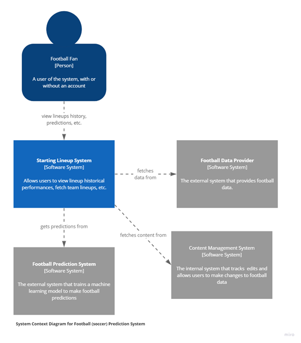
The C4 model starts with the System Context Diagram as a foundational view into the system. Context is level 1. It gives the bird’s eye view of th internal and external systems.
The following System Context diagram illustrates the point by giving a broad overview of my football prediction system.
Next is the Container Diagram which delves into the core components of the system. The Container is level 2. Containers are bundles of code and other data required to execute an application. They also show which technology will be used.

The Component Diagram, on level 3, shows the components within a container, what they are, their responsibilities and implementation details.

At this point, we are supposed to be discussing level 4 which is the Code level but since this design document will be divided into HLD and LLD. Anything to do with code will be put into the LLD.
Well, that’s it as far as the C4 Model is concerned for my web application. The C4 model does allow for a deployment diagram that allows you to illustrate how instances of software systems and/or containers in the static model are deployed on to the infrastructure within a given deployment environment (e.g. production, staging, development, etc.). This is where I might have included infrastructure nodes such as DNS services, load balancers, firewalls, etc.
I am happy with the level of abstraction, levels 1 to 4 give so far. I will leave deployment for now.
Low Level Design
As stated in the previous article, as per Geeksforgeeks, LLD, or Low-Level Design, is a phase in the software development process where detailed system components and their interactions are specified. It involves converting the high-level design into a more detailed blueprint, addressing specific algorithms, data structures, and interfaces.
The LLD is the detailed design of the system. It looks at the internal structure of each component. I have decided that for the purposes of this article level 4, the Code level of the C4 Model, belongs in the LLD. A number of UML diagrams will be used to document coding decisions pertaining to the system.
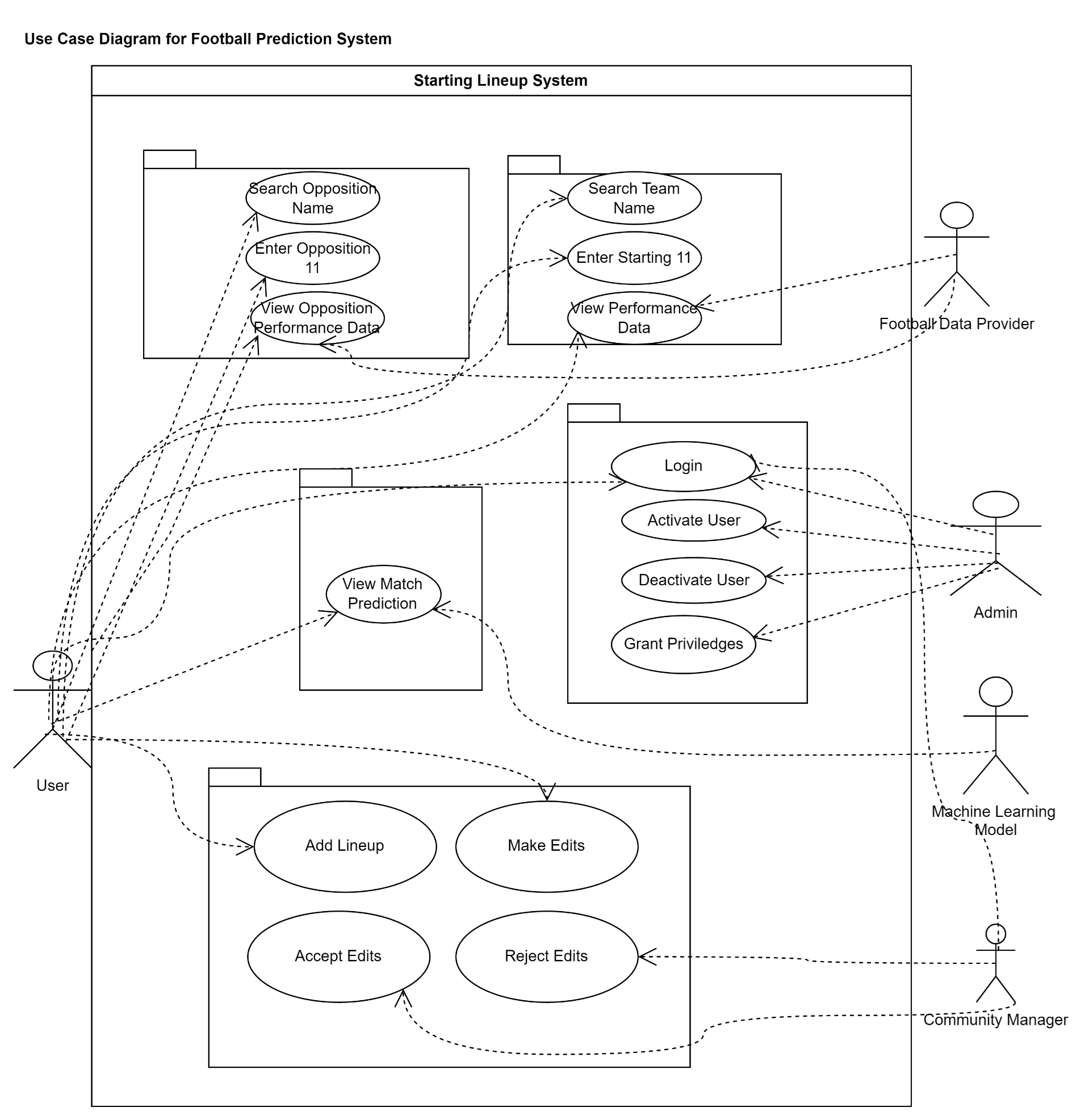
To get us going we will revisit the use cases listed earlier. We will be depicting them in a use case diagram. According to Wikipedia, a use case diagram is a graphical depiction of a user's possible interactions with a system. To create a use case diagram, you start off by identifying the actors (users) of the system. Identify their role(s). Identify what the users require the system to do to achieve their goals. Create use cases for every goal. Rinse and repeat as you go along.
There are three main use cases for my football prediction app as previously identified:
Lineup Lookup
Opposition Lookup
Match Prediction
The main actor is the User. However, this is not where it ends. Upon further analysis, it turned out that another actor was the Administrator.
So a further use case, belonging to the Administrator, is:
- Manage Users
While conducting analysis of the system, I considered that football data might not be readily available, so why not make the User a football data provider?
So now two important use cases for the User become:
Edit Lineups
Add Lineups
In which case, now either the system automatically accepts the edits or another task(s) gets added to the Administrator’s responsibilities and which is:
Accept Edits
Reject Edits
These are the most important uses of the system. And so the use case diagram “should” look something like this:
That was rather messy. Still, it’s something.
So next we move onto the class diagram.
According to Wikipedia, in software engineering, a class diagram in the Unified Modeling Language (UML) is a type of static structure diagram that describes the structure of a system by showing the system's classes, their attributes, operations (or methods), and the relationships among objects.
In order to draw a class diagram, you first identify the primary objects of the system. Next, determine how each of the classes or objects are related to one another. And finally add the class names and appropriate connectors.
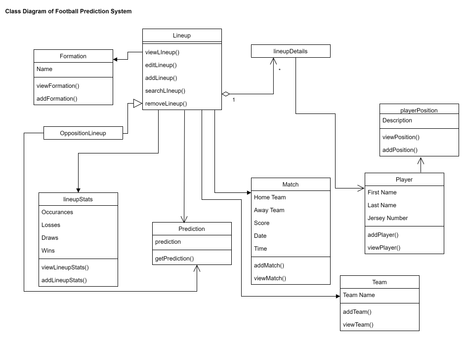
Keep in mind that the preceding Class diagram is a first draft, so things might change somewhat. Also, I did not include all the detail, only what I thought will be necessary at this stage.
Next up is the Sequence diagram. According to Wikipedia, in software engineering, a sequence diagram shows process interactions arranged in time sequence. This diagram depicts the processes and objects involved and the sequence of messages exchanged as needed to carry out the functionality.
The major use case of this football prediction system is viewing a match prediction between two starting lineups. Just to recap:
A User sends a request to the Starting Lineup System to view a particular team.
The System fetches the previous starting lineup and performance data of that team from an external Football Data Provider.
Should the Football Data Provider not provide the required data, the System retrieves the data from an internal Football Database.
The System then responds to the User by displaying the last lineup and performance data of the requested team.
The User then enters the desired starting lineup and submits.
The System fetches the desired starting lineup and performance data from an external Football Data Provider.
Should the Football Data Provider not provide the required data, the System retrieves the data from an internal Football Database.
The System then responds to the User by displaying the performance data of the desired lineup.
The User then enters the name of the opposition team and submits.
The System then fetches the previous starting lineup and performance data of the opposition team from an external Football Data Provider.
Should the Football Data Provider not provide the required data, the System retrieves the data from an internal Football Database.
The System then responds to the User by displaying the last lineup and performance data of the requested team.
The User enters the desired opposition starting lineup and submits.
The System fetches the desired opposition starting lineup and performance data from an external Football Data Provider.
Should the Football Data Provider not provide the required data, the System retrieves the data from an internal Football Database.
The System then responds to the User by displaying the performance data of the desired opposition lineup.
The User requests a prediction of a match between the team and the opposition starting lineups.
The System requests a prediction from an external Machine Learning Model.
The System then displays the prediction to the User.
So this is what that all looks like in a diagram:

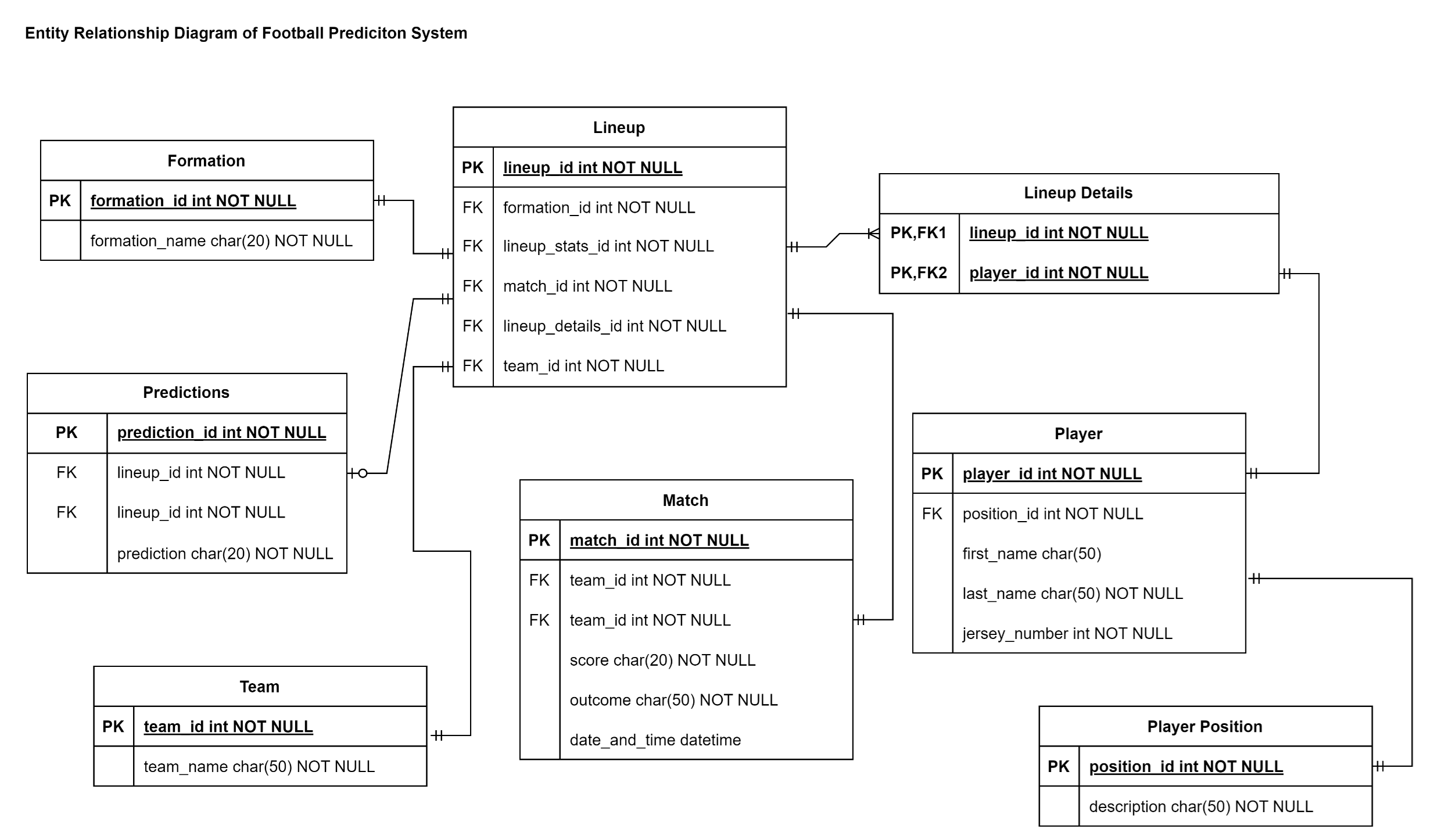
Next up, the Entity Relationship Diagram (ERD). According to Geeksforgeeks:
The Entity Relationship Diagram explains the relationship among the entities present in the database. ER models are used to model real-world objects like a person, a car, or a company and the relation between these real-world objects. In short, the ER Diagram is the structural format of the database.
Keep in mind that for this system the database acts as a backup for when the external third party API is not particularly helpful.
Final Thoughts
This concludes the system design of my football prediction app. This process took longer than I expected but it was illuminating. I am confident it will save me a lot of work down the line.
The next article will focus on the UI/UX design. I might give myself more than two weeks to sit down and work on it. Allowing for my schedule and research.
I am happy with how this is shaping up, I look forward to working on the look and feel of the app.
Subscribe to my newsletter
Read articles from SK directly inside your inbox. Subscribe to the newsletter, and don't miss out.
Written by

SK
SK
I am aspiring to be a well-rounded full stack developer and data engineer. I am currently enrolled for BSc Mathematics and Computer Science. I have recently added AWS Certified Cloud Practitioner to my arsenal.