Render Text via Direct Context 3D
 Moustafa Khalil
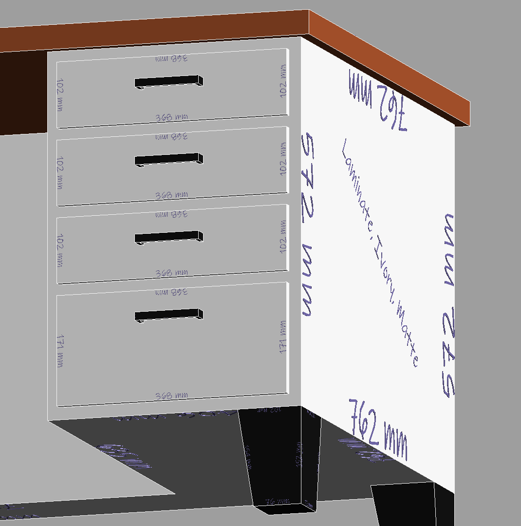
Rendering text in the Revit API using DirectContext3D can be approached in several ways, each with its advantages and limitations. Here, we explore two methods: FormattedTextand GraphicsPath.
FormattedText
FormattedText.BuildGeometry is a practical choice for rendering text. It converts text into a geometry that can be rendered in 3D. However, it doesn't always match the font shape perfectly, but it offers acceptable performance for many applications.
Advantages:
Better performance.
Simpler implementation.
Generates a reasonable approximation of text shapes.
Disadvantages:
Limited accuracy in matching the font's exact shape.
Converts curves to polyline segments, which might not always be desirable.
Implementation Example:
List<CurveLoop> rvtCurves = [];

    var formatted = fontSettings.GetFormattedText(message);
    GeometryGroup geo = formatted.BuildGeometry(new System.Windows.Point()) as GeometryGroup;
    var pathGeometry = geo.GetFlattenedPathGeometry();

    foreach (var fig in pathGeometry.Figures)
    {
        var cloop = new CurveLoop();

        XYZ startPoint = fig.StartPoint.ToRvtPoint();
        for (int i = 0; i < fig.Segments.Count; i++)
        {
            PathSegment seg = fig.Segments[i];
            try
            {
                Curve curve = null;
                if (seg is LineSegment lineSeg)
                {
                    curve = Line.CreateBound(startPoint, lineSeg.Point.ToRvtPoint());
                }
                else if (seg is BezierSegment bezSeg)
                {
                    var p0 = startPoint;
                    var p1 = bezSeg.Point1.ToRvtPoint();
                    var p2 = bezSeg.Point2.ToRvtPoint();
                    var p3 = bezSeg.Point3.ToRvtPoint();
                    curve = HermiteSpline.Create([p0, p1, p2, p3], false);
                }
                else if (seg is PolyLineSegment polSeg)
                {
                    var points = polSeg.Points.Select(o => o.ToRvtPoint()).ToList();
                    points.Insert(0, startPoint);
                    foreach (var item in points.DrawAPI(false))
                    {
                        cloop.Append(item);
                    }
                }
                else if (seg is PolyBezierSegment polBezSeg)
                {
                    var points = polBezSeg.Points.Select(o => o.ToRvtPoint()).ToList();
                    points.Insert(0, startPoint);
                    var tangents = new HermiteSplineTangents();
                    tangents.StartTangent = (points[1] - points[0]).Normalize();
                    tangents.EndTangent = (points[3] - points[2]).Normalize();
                    curve = HermiteSpline.Create([points[0], points[3]], periodic: false, tangents);
                    cloop.Append(curve);
                }
                else
                {
                    // Unsupported type yet
                }

                if (curve != null)
                {
                    cloop.Append(curve);
                    startPoint = curve.GetEndPoint(1);
                }
            }
            catch (Exception ex)
            {
                // something went wrong
            }
        }

        rvtCurves.Add(cloop);
    }
}
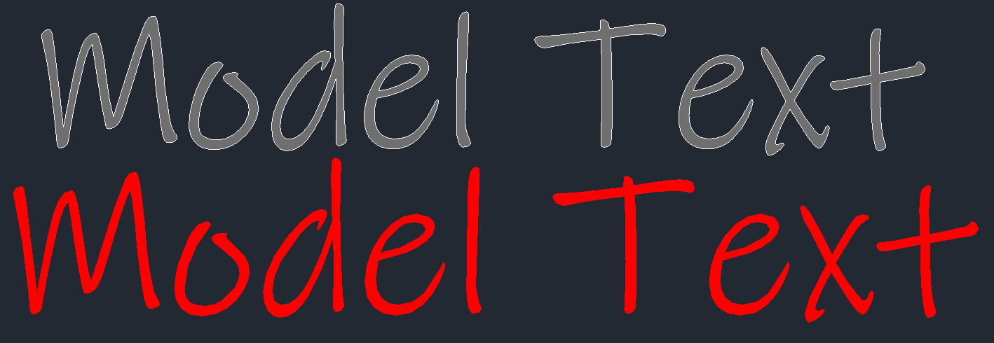
GraphicsPath offers a closer match to the original font shapes but at a significant cost in terms of performance. It generates a higher number of points and curves, leading to a denser and more accurate geometry representation.
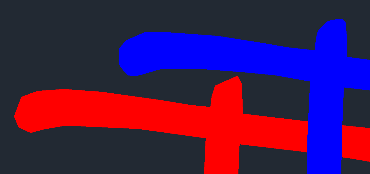
Red is FormattedText
Blue is GraphicsPath
Advantages:
Higher accuracy in font shape rendering.
Better for applications where visual fidelity is critical.
Disadvantages:
Higher computational cost.
Increased number of faces and points can lead to performance issues.
Implementation example
List<CurveLoop> rvtCurveLoops = [];
try
{
    // Create a GraphicsPath object
    GraphicsPath path = new GraphicsPath();
    path.AddString(
        message,
        new System.Drawing.FontFamily(fontSettings.Family.FamilyNames.First().Value),
        (int)fontSettings.FontStyle,
        fontSettings.FontSize,
        new PointF(),
        StringFormat.GenericDefault
    );

    // Create lists to hold points and types
    PointF[] points = path.PathPoints;
    byte[] types = path.PathTypes;

    // Initialize a list to hold the resulting Revit curves
    List<Curve> revitCurves = new List<Curve>();

    // Temporary lists to store points for each curve
    List<XYZ> linePoints = new List<XYZ>();
    List<XYZ> BezierPoints = new List<XYZ>();

    XYZ startPoint = points[0].ToRvtPoint();

    for (int i = 1; i < points.Length; i++)
    {
        // Convert PointF to XYZ
        XYZ point = points[i].ToRvtPoint();
        byte type = types[i];

        switch (type)
        {
            case (byte)PathPointType.Start:

                startPoint = point;
                if (revitCurves.Any())
                {
                    rvtCurveLoops.Add( CurveLoop.Create(revitCurves));
                    revitCurves.Clear();
                }
                break;

            case (byte)PathPointType.Line:
                linePoints.Add(startPoint);
                linePoints.Add(point);
                startPoint = linePoints.Last();

                AddLineCurves(linePoints, revitCurves);
                linePoints.Clear();
                break;

            case (byte)PathPointType.Bezier3:
                BezierPoints.Add(startPoint);
                BezierPoints.Add(point);
                BezierPoints.Add(points[++i].ToRvtPoint());
                BezierPoints.Add(points[++i].ToRvtPoint());
                startPoint = BezierPoints.Last();
                AddBezierCurves(BezierPoints, revitCurves);
                BezierPoints.Clear();
                break;

            case (byte)PathPointType.CloseSubpath:
                   // $"{PathPointType.CloseSubpath} not implemented"
                break;

            case (byte)PathPointType.PathMarker:
                    //$"{PathPointType.PathMarker} not implemented"
                break;

            case (byte)PathPointType.DashMode:
                    //$"{PathPointType.DashMode} not implemented"
                break;

            default:
                // Handle any other types if necessary
                break;
        }
    }
    if (revitCurves.Any())
    {
         rvtCurveLoops.Add( CurveLoop.Create(revitCurves));
    }

    return rvtCurveLoops;
Performance Comparison:
GraphicsPath Method:
Points: 104
Curves: 35
FormattedText Method:
Points: 47
Curves: 47
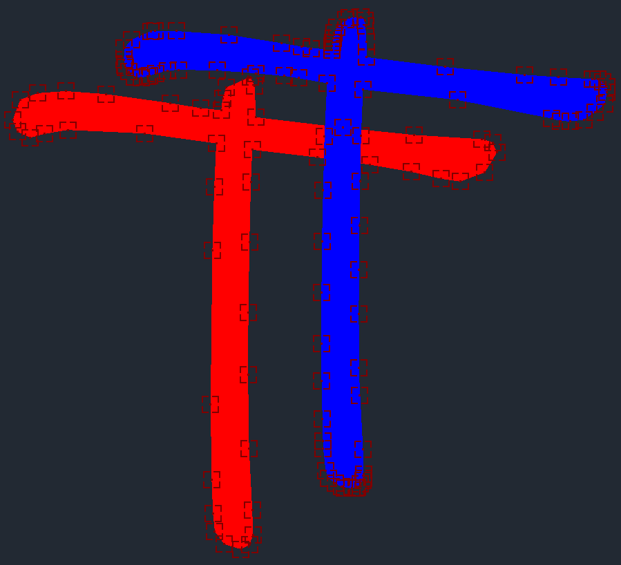
Example Results:
Red: FormattedText output.
Blue: GraphicsPath output.
font used: Ink Free
In conclusion, while FormattedText.BuildGeometry offers better performance, GraphicsPath provides more accurate text shapes. The choice between them depends on the specific requirements of accuracy versus performance in your application.
Red is FormattedText
Blue is GraphicsPath
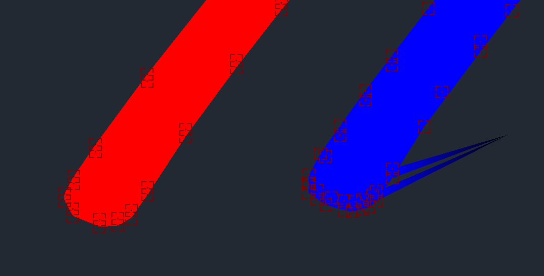
However using GraphicsPath, usually returns a broken graphics, not sure why yet.
Edit 11th June
I was able to realize the why FormattedText shows different optimized shape than GraphicsPath, due to the face we are using this statement
var pathGeometry = geo.GetFlattenedPathGeometry();
This statement accoriding to Documentation The polygonal approximation of the geometry. thus if we changed the tollerance of flattening, it would return a better result.
 var figures = geo.GetFlattenedPathGeometry(.00001, ToleranceType.Relative)
                  .Figures;

This is using FormattedText with flattengeometry of .00001 almost the maximum. which returned exactly what is expected
Now we play with tolerance to suit the performance against quality as it is always every developer challenge
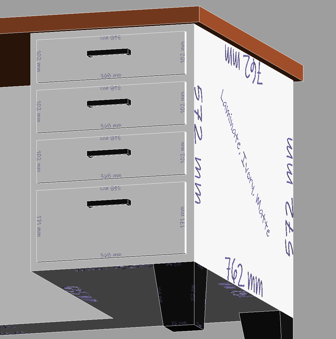
Forgot to mention... that when converting to solid, then we can have what the font size is actually rendered on revit. due to the fact that each font scales differently, we can use Transform.ScaleBasis(value), in the direct context 3D, to scale it to the size we need saying intendedWidth should be 1 meter long
// extention function are helpful here
scale = intendedWidth/textSolid.GetBoundingBox().Width;
an example of how text can be helpful during design
Subscribe to my newsletter
Read articles from Moustafa Khalil directly inside your inbox. Subscribe to the newsletter, and don't miss out.
Written by

Moustafa Khalil
Moustafa Khalil
I'm Moustafa Khalil El-Sayed, an Egyptian native with a passion for architecture and technology. After completing high school in 1999, I embarked on my journey into architecture, earning my Bachelor's degree in Architecture in 2004. My academic pursuits continued, and I later acquired my Master's degree in Architecture from Wings University. However, my thirst for knowledge extended beyond architectural design, leading me to pursue a degree in Computer Science as well. Driven by a desire to innovate, I began self-teaching computer science, which later empowered me to achieve my Associate degree in Computer Science from the University of the People more easily. Armed with dual expertise in architecture and computer science, I've cultivated a unique skill set that blends creativity with technical acumen. My career has taken me across borders, from Egypt to Oman and the UAE, where I've honed my skills as an architect. As a graduate architect and a proficient .NET BIM Solution Developer, I specialize in translating unique visions into tangible realities. My role extends beyond conventional architectural practices; I leverage technology to streamline processes and enhance project outcomes. My journey into programming began with developing script-based Excel tools to augment project management efforts, notably during the Sharm El Sheikh development. Over time, I expanded my programming prowess to address practical challenges encountered in bridging Revit and AutoCAD within my professional sphere. Several of my applications, born from this evolution, have gained recognition, with some even being featured on the Autodesk website. I am committed to pushing boundaries and continually enriching the intersection of architecture and technology, ensuring that my clients benefit from cutting-edge solutions tailored to their needs.