How to Build a Laser Projector: Step-by-Step Guide
 Shoaib
Table of contents
In an attempt to create multi-coloured laser beams combined and then projected onto the screen with a galvanomirror and an STM32 microcontroller, I will be working on the STM32 part. Here, I'll figure out the firmware needed to steer the combined laser beam and change colours as desired.
STM Timer module
Timer module in be in several different types
timer mode TCNT register gets incremented by 1 after every clock cycle. the oscillating source goes through prescaler and then increments after every clock cycle. this mode can give an overflow interrupt when register is full. usually at 80Mhz and 1:1024 prescaler it's 0.89seconds. but if we want the interrupt to occure every 1 second.. we can use the preloader to not start the count from 0 but from some other value.
counter mode Instead of clock source can take any input and at rising or falling edge of signal the TCNT register increments by one. note that in this mode it also goes through the prescaler so we can set that to 1:1 to get real value
general timer moduleall timer module consists of counter register, Auto-reload register with a preload register access and prescaler register.
PWM Mode of timer moduleIn PWM mode
The timer module can operate in several different modes:
Timer Mode:
In this mode, the TCNT register increments by 1 after every clock cycle. The oscillating source goes through a prescaler and then increments after each clock cycle. This mode can trigger an overflow interrupt when the register is full. For example, at 80MHz with a 1:1024 prescaler, this occurs every 0.89 seconds. If we want the interrupt to occur every 1 second, we can use the preloader to start the count from a value other than 0.
Counter Mode:
Instead of using a clock source, this mode can take any input and increment the TCNT register by one at each rising or falling edge of the signal. Note that this mode also uses the prescaler, so we can set it to 1:1 to get the real value.
General Timer Module:
All timer modules consist of a counter register, an auto-reload register with a preload register access, and a prescaler register.
PWM Mode of Timer Module:
In PWM mode, the timer module is clocked from an internal clock source and produces a digital waveform on the output channel pin, called the PWM signal. By using output compare registers (OCR), the incrementing timer’s register value is constantly compared against this OCR register. When a match occurs, the output pin state is flipped until the end of the period, and the whole process is repeated.
The timer in PWM mode will produce a PWM signal at the specified frequency chosen by the user. The duty cycle is also programmatically controlled by its register. The PWM resolution is affected by the desired FPWM and other factors, as we’ll see in the dedicated tutorials for PWM generation.
I'll be following "Discovering the STM32 Microcontroller" by Geoffrey Brown to get a better understanding of this controller. Too many concepts are flying over my head right now.
Update Thu/27/June/2024 PWM working now
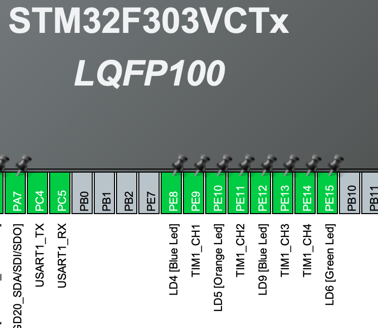
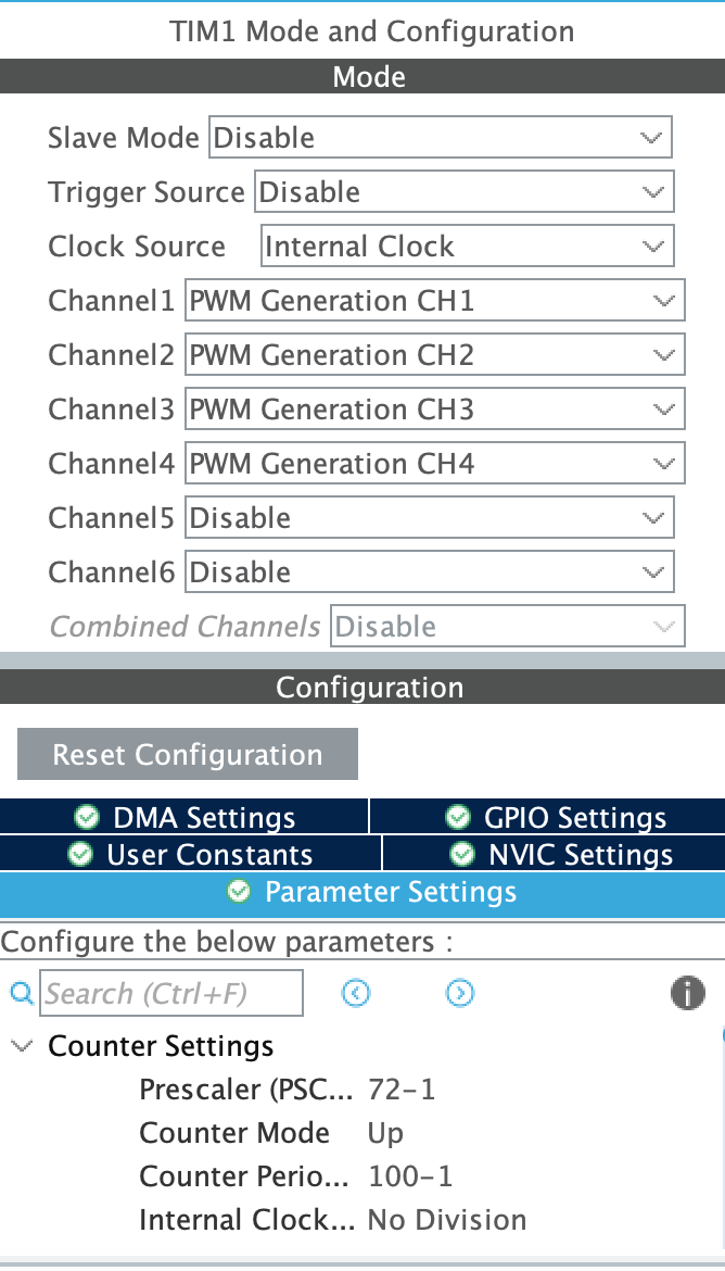
The pins are just outlets; the main work is done by the clock. I had to select a pin and see which timer it was attached to. These ones are all attached to timer 1, namely channels 1, 2, and 3. I enabled all of them one by one, chose the clock source as internal since the board I'm using does not have an external source. Then I selected the following settings, noting the prescaler and period value. That defined the frequency I would get. The equation is something like this (note you have to figure out which timer corresponds to which APB and use that speed instead of the system clock if it's different).
frequency = APB1 clock speed (not system) / ((Prescaler + 1) * (Period + 1)) In my case, it was = 72 MHz / (72 * 100) = 10 kHz If I want a 1 kHz signal, I only need to change the Period. So the equation becomes: Period + 1 = APB1 clock / (frequency * (Prescaler + 1)) So it should give me: Period + 1 = 72 MHz / (1 kHz * (71 + 1)) Period = 999 + 1 - 1 = 999
I checked with an oscilloscope, and it indeed was giving the desired frequency! But I switched to STM32 to enjoy 16-bit PWM with possible values of 0-65535. Yet, I'm not sure if it generates the 1 kHz signal with 16-bit or not. Let's find out.
The formula to find the resolution is as follows: Resolution (R) = log(ARR (Period) + 1) So R = log(999 + 1) R = 9.97, approximately 10 bits, which is still better than 8 bits that gave 256 possible values. But this will give 2^10 = 1024 discrete steps. I wonder if there is a way to get to 16 bits while having the same frequency? My question is, why would the frequency of the signal matter while we are only looking at the duty cycle?
The pins were selected as:
The settings of pwm channel was done as:
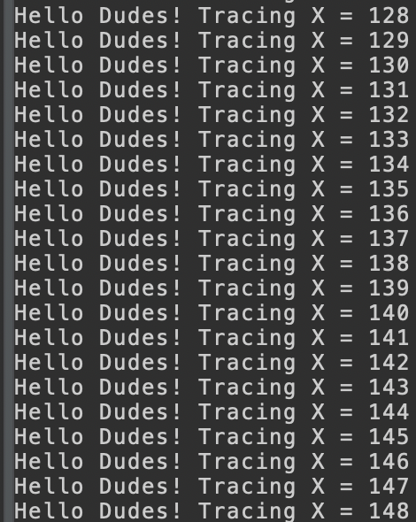
Serial debugging working Thu/27/June/2024
I was thinking it might not be possible to get serial messages given that debugging was available. but to my surprise because of the presence of stlink programmer on board of F3-discovery board it gave me an access to virtual com port that was using the same com port as used by ide to program it. after enabling the UART1 in asynchronous mode i opened serial console within the ide and started the connection.
UPDATE Fri/28/June/2024 Tested the pwm with a green laser with a transistor (2n222) in between it and the microcontroller.
At 1 kHz, the laser did not turn on. It turned on at higher frequencies. I tested it with 10 kHz, and it worked. So, I guess my theory about the frequency not making a difference was wrong. I wonder if a MOSFET will behave differently? I'll try.
Green Laser: The supply to the laser is set at 6V 400mA max. The laser at 100% duty cycle is taking 350mA max. The laser barely turns on at ARR = 13 but is steadily on with a dim beam at ARR = 15 or 15% duty cycle. I still need to figure out the minimum value it will take to turn on and adjust all my future PWM signals accordingly.
For further tests, I need an easy way to control the PWM signal. Right now, I'm just uploading the program repeatedly with changed values. I think a potentiometer might work if I can map it to the ARR value.
PS: Although the laser is common and weak, I feel my eyes straining when working near it. Well, it seems like 6V @ 350mA is 2W and is not common. Never mind, I found glasses and will wear them from now on. Haha!
A question: Can I set only 0-100 value in CCR, and would that correspond to the duty cycle? No. CCR can be set from 0 to the value of ARR. In the case of 1000 ARR, it would range from 0-1000. CCR is used to control the duty cycle. This value is compared with the ARR value to generate a certain duty cycle (D).
$$D = \frac{CCR}{ARR + 1} \times 100\%$$
UPDATE 3/JULY/2024 Did spectroscopy!
Since my project involves changing and understanding CIE coordinates of colors and converting those values to the appropriate PWM signal for the lasers to produce a desired colour, I had to find the exact wavelengths of the lasers I was using. For this, I used a USB2000+ spectrometer from Ocean Optics. A spectrometer essentially tells you where the incident light falls on the wavelength scale and what the intensity or saturation is.

I first tested with the green laser. It was problematic at first, showing multiple peaks, which led us to conclude that the laser needs to be pointed exactly at the slit. Any slight deviation would result in multiple peaks. However, even after multiple adjustments, we couldn't eliminate an IR peak at around 800nm, which shouldn't be there. It wasn't present with other lights, just with this laser.
It seems that the peak needs to be smooth with no sharp edges for an accurate measurement. This can be fixed by reducing the intensity of the laser. I placed a diffuser in the light path and reduced the laser's duty cycle to a value of 30 to get good results. Here is the result from the data captured with the spectrometer.
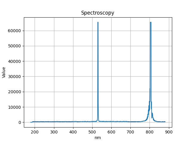
We can ignore the rest and focus on the fact that at 528.455nm, it showed the highest saturation. To verify the results, I searched and confirmed that it was correct. However, there is still the question of the 800nm peak. It did not occur with other lasers or normal light, only with this green laser. This peak is in the IR region and is likely related to the construction of the laser itself.

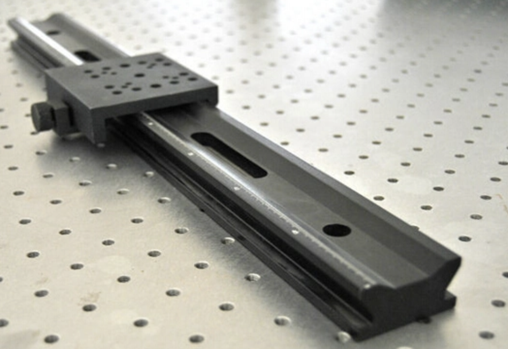
setting the usb2000+ inline with the beam was hard, the optical table did not have holes where i wanted them.. so i used a railing to put everything on it inline.. i then only had to change the vertical axis to bring it inline with the beam..
Next i have to find a way to generate PWM signal of the three lasers combined to result in a specific CIE coordinate. ofcourse i'll start with one color first. say different shades of green will have different cie coordinates and that can be acheived with pwm duty cycle? i'm not sure gotta check.
Subscribe to my newsletter
Read articles from Shoaib directly inside your inbox. Subscribe to the newsletter, and don't miss out.
Written by
