Day 4 - Network Cabling and Topologies
 Shreyas Ladhe
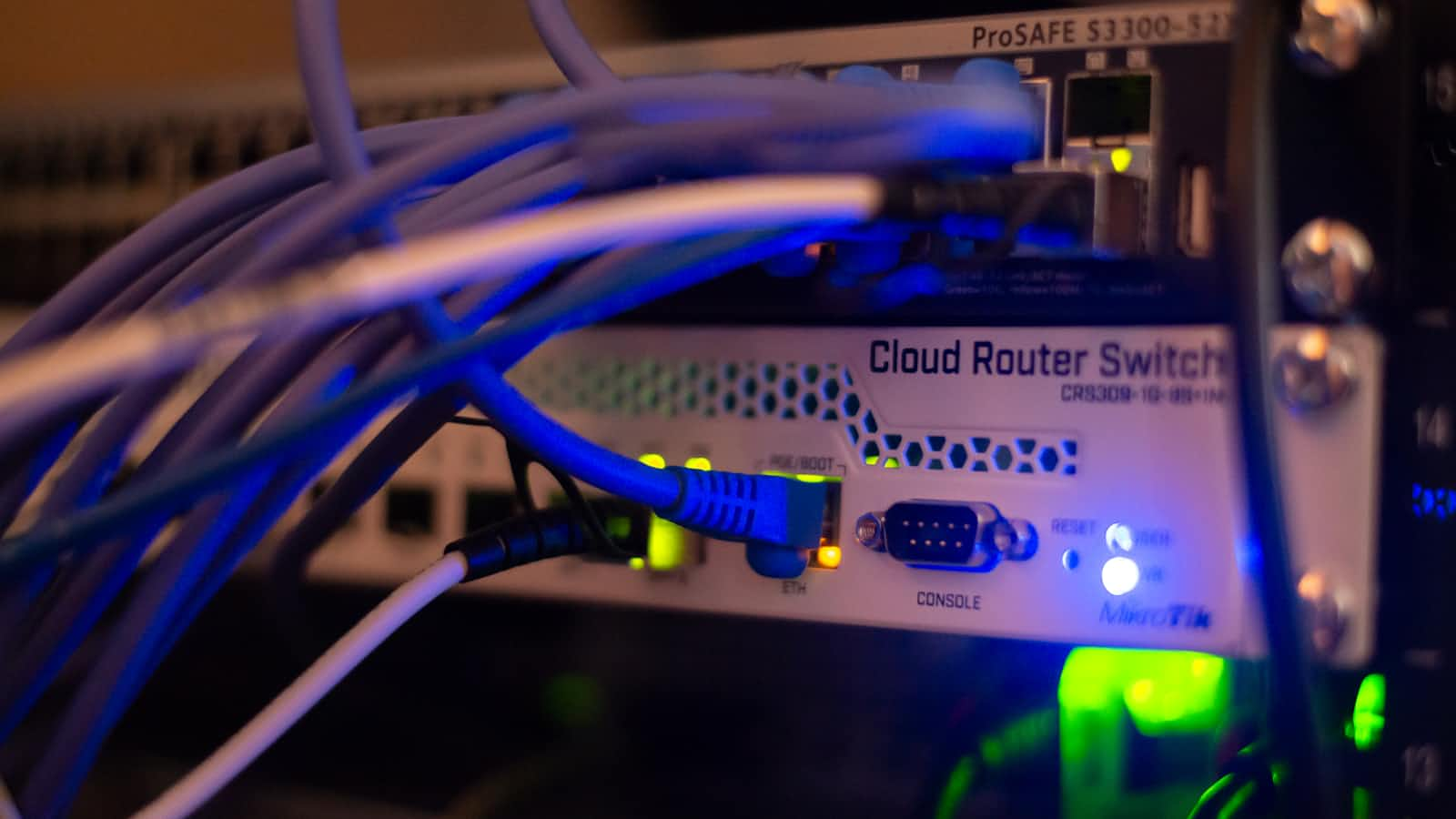
Network Cabling
Twisted Pair Network Cabling
Most people are familiar with twisted pair cables, as they are the standard in the modern LAN.
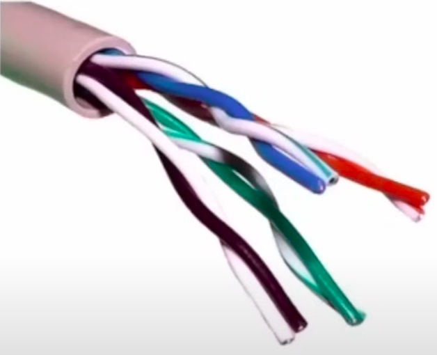
Twisted pair cables are composed of four pairs of wires contained within an insulating sheath Each pair of wires is twisted together to reduce electromagnetic interference (EMI) The twist rates differ between the pairs of wires to reduce cross-talk between the pairs The colors of the pairs are white orange/orange, white blue/blue, white green/green, and white brown/brown.
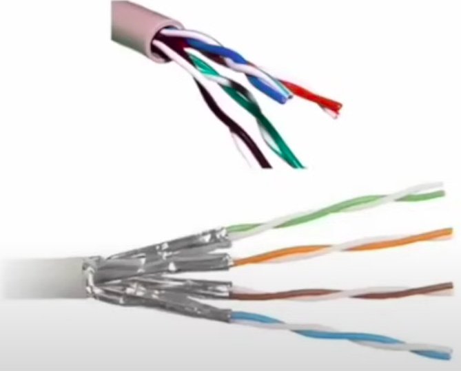
Unshielded vs. shielded twisted pair (UTP vs. STP)
STP has an additional shield that is ether wrapped around each pair of wires or around all four pairs.
- STP reduces the opportunity for EMI or cross-talk, but is more expensive and a little harder to work with.
UTP is deployed in the network much more often than STP.
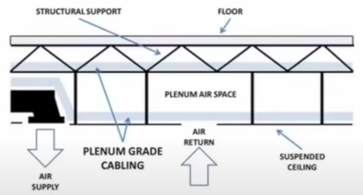
Plenum vs. non-plenum twisted pair
Most twisted pair is non-plenum grade
Building codes often call for plenum grade cable to be run in plenum spaces (areas designed to assist in the airflow of a building for HVAC purposes)
Plenum cable is jacketed in either a fire-retardant cover or in a low-smoke PVC jacket.
Plenum cable often has a polymer or nylon strand woven into it to help take the weight of hanging cables. This reduces the chance for the cable to stretch, which can cause the pair inside to break.
Twisted pair is usually either a straight-through cable or a crossover cable, but it can also be used to create a rollover (console) cable.
A straight-through cable is used to connect different types of devices together (computer to switch or switch to router) while a crossover cable is used to connect similar devices together (PC to PC, or switch to switch) They use a different pin out to achieve the connection
A rollover or console cable is often required to connect to the console port on a switch or router; it is quite common for one end of the rollover cable to use an RJ45 connector, while the other end utilizes an RS 232 (DB 9) connector.
Twisted Pair network connectors
RJ11
(Uses a six-position four-contact (GP4C) modular connector.
Can carry data or voice, common usage is voice communication (telephony)
RJ45
Uses an eight-position eight-contact (8P8C) modular connector.
Can carry data or voice, common usage is data networking (Ethernet).
RJ48C
Uses an eight-position eight-contact (8P8C) modular connector.
Used as the terminating connector at the demarc for T1 lines.
- It is often confused with an RJ45, but the active pins are different.
UTP coupler
- Used to connect UTP cables back to back and still maintain adherence to industry standards.
66 block
A punch down block initially developed to terminate and distribute telephone lines in an enterprise environment.
- It was also used in slower speed networks, as it can handle data traffic rated for Cat 3 cabling.
110 block
- A punch down block developed to terminate and distribute twisted pair network cabling. It is capable of handling the signaling requirements of the modern network.
DB9 (RS-232)
A nine pin D-subminiature connector developed for asynchronous serial communication between nodes.
It was a common type of connection between a computer and an external analog modem.
It often makes up one end of the rollover cable.
DB25 (EIA-232/RS-232 serial)
A 25 pin D0-subminiature connector developed for asynchronous serial communication between nodes.
- It was a type of connection between a computer and an external analog modem.
Categories of Twisted Pair
Cat 3
Rated for up to 10 Mbps speed, 10BaseT.
- Max distance of 100 meters.
Cat 5
- Rated for up to 100 Mbps speed, 100BaseT.
Cat 5e
- Rated for up to 1 Gbps, 1000BaseT.
Cat 6
Rated for up to 10 Gbps, 10 Gigabit Ethernet (GbE).
- Max distance of 55 meters when used for 10 GbE.
Cat 6a
Rated for up to 10 Gbps, 10 Gigabit Ethernet (GbE).
- Max distance of 100 meters when used for 10 GbE.

Coaxial Cabling
Coaxial cabling
Coaxial cabling ts one of the oldest Ethernet cabling standards (1973).
It has been used for baseband (carries single digital signal).
It has been used for broadband (carries multiple digital signals).
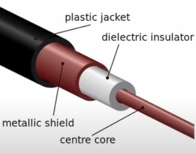
It is composed of a central conductor that is covered by an insulating layer, which ts covered by an outer metal mesh or foil layer that is finished with an outer insulating layer
The inner metal mesh or foil layer helps to protect against EMI.
Coaxial cable types
RG58: 10Base2, max distance of 185 m, 50 ohms impedance.
- No longer commonly found in the modern network.
RG59: Commonly used to provide a broadband connection between two devices over a short distance, has a 75 ohms impedance value.
RG6: cable TV or broadband, distance varies, has a 75 ohms impedance value.
- Commonly used to make the connection to cable modems by cable companies.
Coaxial cable connectors
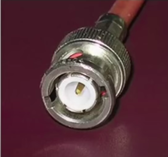
BNC (Bayonet Neill-Concelman)
Also known as a bayonet connector.
Used with coaxial cable; is now considered obsolete.
The connection from the cable to the device was achieved through a twist-lock type connection.
A BNC coupler can be used to connect two coaxial cable segments back to back.
F connector
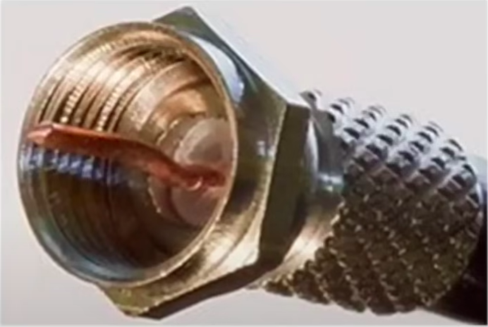
A threaded bayonet connector.
Used with coaxial cable.
A F connector coupler can be used to connect two coaxial cable segments back to back.
Fiber Optic Cabling
Fiber optic cabling described
It is relatively expensive and harder to work with.
It is not that common in the LAN environment
It resists all forms of EMI and cannot be easily tapped.
It can cover long distances at high speed.
It is designated by fiber type, cladding size (the cladding is what the light bounces down), and jacket size.
- Size of cladding and jacket listed in micrometers.
Most applications require that fiber cables be run in pairs. (basically a send cable and a receive cable).
The type of connector used on fiber optic cabling can impact the performance of the transmissions.
The UPC (Ultra Physical Contact) connector has a back reflection rating of around -55 dB.
The APC (Angled Physical Contact) connector has a back reflection rating of around -70 dB, making it the better performing connector.
Fiber types
Multimode fiber (MMF)
It uses an infrared LED system to transmit the light
It uses multiple rays of light going down the cable.
It is used for shorter fiber runs, under 2 km.
It is less expensive to implement than SMF.
The most common application in networking is MMF 62.5/125u, which is good for up to 275 m.
Single-mode fiber (SMF)
It uses a laser-diode arrangement to transmit the light.
It uses a single ray of light transmitted down the cable.
It is used for longer runs that require high speed.
It can traverse 40+ km.
Fiber optic cabling connectors
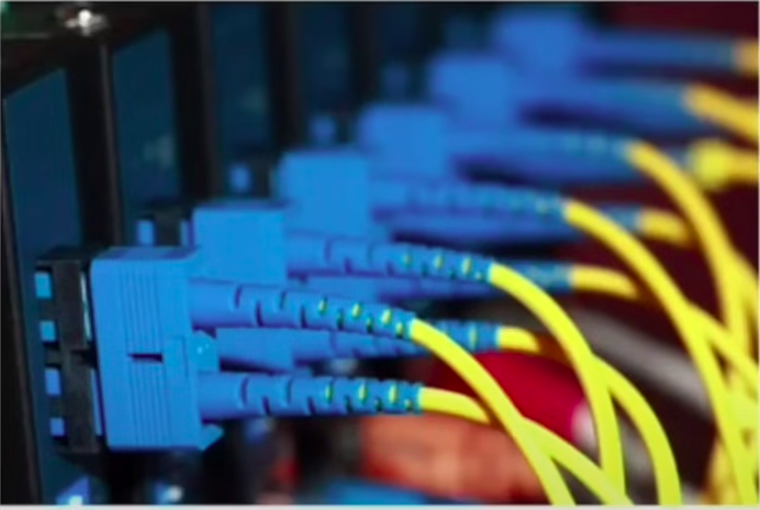
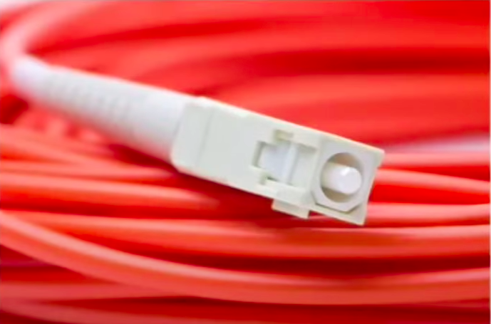
SC
Subscriber Connector, or Square Connector, or Standard Connector (Stick and Click).
A push-pull type of connector.
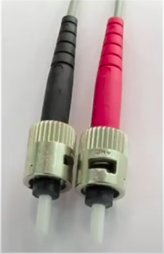
ST
Straight Tip (Stick and Twist)
A twist lock type of connector.
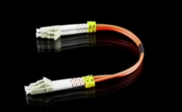
LC
Local Connector, or Lucent Connector, or Little Connector.
A type of connector that uses a locking tab to secure the connection.
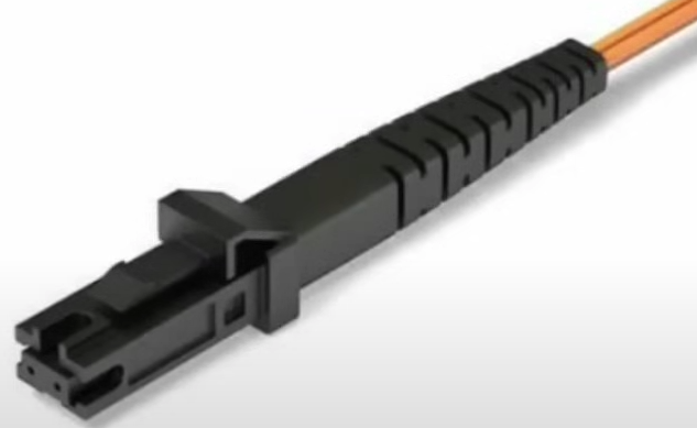
MTRJ
Mechanical Transfer Registered Jack.
A small form factor connector that contains two fibers and that utilizes a locking tab to secure the connection.
Fiber optic coupler
- Used to connect two fiber optic cables back to back.
Network Topologies
What is a topology
A topology is basically a “map” that can describe how a network ts laid out or how the network functions.
The network topology can be described as either logical or physical. A logical topology describes the theoretical signal path while the physical topology describes the physical layout of the network.
Peer to Peer vs client/server
Are these really topologies?
- No. they don’t describe the signal path or the physical layout of the network Yes they describe the how the network functions
Peer-to-peer topology
Nodes control & grant access to resources on the network.
No 1 node or group of nodes controls access to a specific type of resources (no server Is present).
Each node is responsible for the resources it is willing to share.
Client/server topology
Network resources access is controlled by a central server(s).
A server(s) determines what resources get shared, who is allowed to use the resources and even when the resources can be used.
Hybrid topology
- A combination of peer-to-peer & client/server networking.
Network Topology Models
The original Ethernet standards established a “bus” topology for the network, both logically & physically.
As time went on the “bus” developed some mechanical problems. That led to the development of different physical topologies, but the logical topology remained the same in order to maintain backward compatibility. So when discussing Ethernet networks, the logical topology is always a “bus” topology while the physical topology can be different.
Bus
The signal traverses from one end of the network to the other.
A break in the line “breaks” the network.
The ends of the “line” must be terminated in order to prevent signal bounce.
The network cable Is the central point.

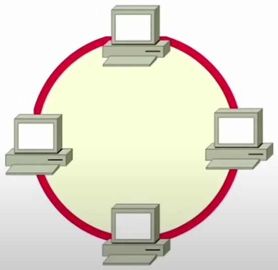
Ring
A bus line with the end points connected together.
A break in the ring breaks the ring.
Often implemented with multiple rings (2) that counter rotate.
Not very common in the LAN anymore, but still used in the WAN (SONET especially).
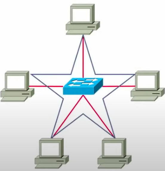
Star
Nodes radiate out from a central point.
When implemented with hubs a break in a segment brings down the bus.
When implemented with a switch, a break in a segment only brings down the segment.
Most common implementation of the modern LAN.
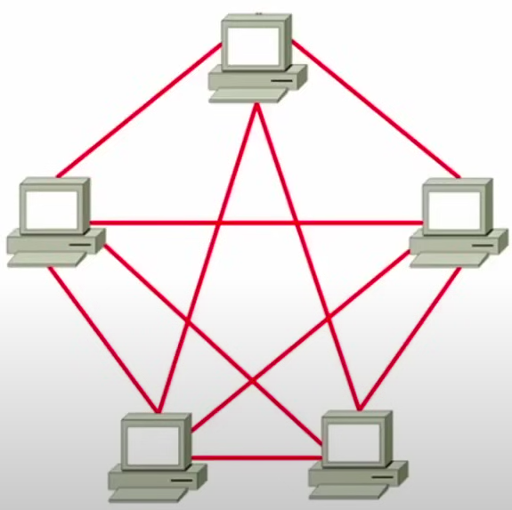
Mesh
Multiple connections between nodes on the network
Full mesh means that every node has a physical connection to every other node.
Partial mesh means that there are multiple paths between nodes.
A full mesh topology is expensive to install because of the wiring constraints.
Point-to-point
Two nodes or systems connected directly together.
Two PCs connected with a crossover cable create a point-to- point topology.
No central device is required to manage the connection.
A common topology when implementing a WAN connection.
Point-to-multipoint
A central device that controls the paths to all other devices.
Differs from a star in that the central device is intelligent.
Wireless networks often implement point-to-multipoint topologies.
When the WAP sends, all devices on the network receive the data, when a device sends it a message is only passed along to the destination.
Also a common topology when implementing a WAN connection.
MPLS
Multiprotocol Label Switching is a topology used to replace both Frame Relay switching and ATM switching.
It’s a topology because it specifies signal path and layout both.
It is used to improve the QoS and flow of network traffic.
Label edge router (LER): adds MPLS labels to incoming packets if they don’t have them.
Label switching router (LSR): forwards packets based on their MPLS labels.
To keep expanding your knowledge base about networking and learning with me. Don't forget to subscribe to my newsletter to receive updates about my new learning everyday. Consider following me on LinkedIn. Want to know more about me!! follow me on Instagram!!
Subscribe to my newsletter
Read articles from Shreyas Ladhe directly inside your inbox. Subscribe to the newsletter, and don't miss out.
Written by

Shreyas Ladhe
Shreyas Ladhe
I am Shreyas Ladhe a pre final year student, an avid cloud devops enthusiast pursuing my B Tech in Computer Science at Indian Institute of Information Technology Vadodara ICD. I love to learn how DevOps tools help automate complex and recurring tasks. I also love to share my knowledge and my project insights openly to promote the open source aspect of the DevOps community.