From C to Assembly
 Ahmed Gouda
Going from C to Assembly
Before we study the syntax (grammar) and semantics (meaning) of assembly instructions, let us first examine the key differences between C and assembly.
C, like many other high-level programming languages, makes powerful abstraction of computer hardware to hide from programmers the details of how computation is implemented. High-level languages make program codes more concise, more portable, and easier to develop and debug.
However, the assembly language, a low-level programming language, offers programmers not only almost complete and fine-grained control of the underlying hardware, but also the flexibility of specifying how a computation should be carried out. Hence, it is often that a well-written assembly program is more efficient than its C counterpart is. Besides abstracting a microprocessor at different levels, some assembly instructions have no equivalent implementation in C.
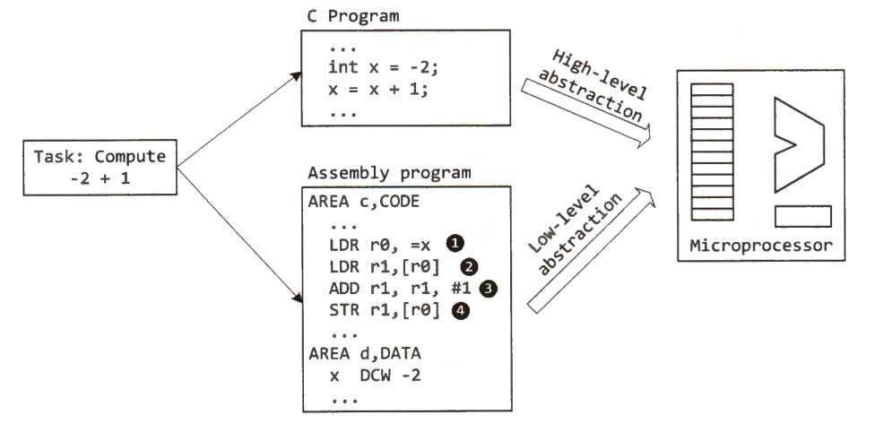
In the below figure, we use a simple example, which computes the sum of two signed integers (1 and -2), to compare the hardware abstraction of C and assembly. We assume the variable x is stored in memory. Note that a variable may be stored in a register instead of in memory to improve the computation speed.

- C abstracts away much detail of complex low-level computing operations. Accordingly, C provides a friendly and convenient programming interface to programmers. Because of strong abstraction, the same C program can be recompiled for two different hardware platforms, as given below:
| Platform 1 | Platform 2 | |
| Signed integer representation | Two's complement | One's complement |
| Size of an integer (bits) | 32 | 16 |
| Operation on immediate numbers? | No | Yes |
| Dat endian | Big endian | Little endian |
In contrast, assembly language requires programmers to understand low-level details of the instruction set that this specific microprocessor supports. For example:
How many bits does an integer take in memory?
What is the data layout of the signed integer x in memory?
How are memory locations specified?
How is the integer x retrieved from memory?
How many operands can an addition support?
How is an overflow or carry handled on an addition?
Instruction Set Architecture Types
In general, there are three types of instruction set architecture (ISA):
Accumulator-Based Instruction Set
One of the ALU source operands is implicitly stored in a special register called accumulator, and the ALU result is saved into the accumulator.
The programmer does not have to specify this operand and the destination register in the program.
The accumulator-based instruction set was popular in the 1950s.
Stack-Based Instruction Set
All ALU operands are assumed to be on top of the stack, and the ALU result is also placed on top of the stack.
The stack is a special region of memory. Thus, programmers need to push the value of operands onto the stack before an ALU operation is called.
The stack-based instruction set was used in the 1960s.
Load-Store Instruction Set
ALU source or destination operands can be any general-purpose registers. ALU cannot directly use data stored in memory as operands.
ALU can only access data in memory by using load or store instructions.
Most modern processors are based on a load-store instruction set.
In the load-store instruction set, many arithmetic and logic instructions typically support two source operands that are stored in registers. The second operand of some instructions can also be a constant number, encoded directly in the instruction.
Load-store instruction set allows effective use of registers.
Compared with the other two types of instruction sets, the load-store instruction set is faster in performance. The accumulator-based instruction set must make an extra copy to store one of the source operands in the accumulator. The performance of a stack-based instruction set is undermined by the performance of memory because ALU must access the memory repeatedly. However, because there are many general-purpose registers available, the load-store instruction set can take full advantage of temporal locality exhibited in almost all applications, effectively reducing the number of accesses to slow memory.
In a load-store instruction set, data stored in memory cannot be ALU operands directly. Therefore, if we want to change some data in memory, software needs to perform a sequence of load-modify-store operations. The software should do the following:
loads target data from memory to a register
modifies the value in the register
stores the new value in the register back to the memory
Example:
int x = -2;
x = x + 1;
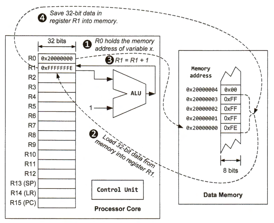
To increment the value of variable x stored in memory by one, a load-modify-store sequence is carried out in four steps in a sequential order:
set up the memory address
load data from memory
perform addition
store new value back to memory
LDR r0, =x      ;Step 1: Setup address (Load memory address of x into r0)
LDR r1, [r0]    ;Step 2: Load (Register r0 holds the memory address of x)
ADD r1, r1, #1  ;Step 3: Modify (Increase the value in register r1 by 1)
STR r1, [r0]    ;Step 4: Store (Save the content in register r1 into memory)

Note an integer takes four bytes in memory. The 32-bit two's complement of -2 is 0xFFFFFFFE. Assume this number is stored in contiguous memory locations, starting at 0x20000000. The second LDR instruction loads this 32-bit integer into register r0 (LDR stands for load register). The last step is to save the 32-bit result (0xFFFFFFFF, i.e., -1) back to the memory region. After these four steps, the byte stored at memory location 0x20000003, 0x20000002, 0x20000001 and 0x20000000 is 0xFF, 0xFF, 0xFF, and 0xFF.
Assembly Instruction Format
A machine instruction consists of:
a binary operation code (opcode) denoting a specific operation to be carried out
zero or more operands specifying the inputs of the operation
In an assembly program, each binary opcode is replaced by its symbolic abbreviation, called instruction mnemonic. Using human-readable mnemonics instead of binary opcode makes developing an assembly program simpler and more convenient.
The general format of an assembly instruction for ARM Keil compilers is as follows:
label
        mnemonic operand1, operand2, operand3    ; comments
- label instruction is a reference to the memory address of this instruction. The assembler either replaces the label with the actual numeric memory address or memory address offset when generating the binary executable. The label is optional and must be unique within the same assembly program file. The label should start at the beginning of a line, without any leading whitespace. The instruction can start a new line, as shown below:
label
mnemonic operand1, operand2, operand3 ; comments
The mnemonic represents the operation to be performed.
The number of operands varies, depending on each instruction. Some instructions have no operands. The comma "," is used to separate operands. Some instruction allows constant numbers (also called immediate numbers) as operands.
operand1 is the destination register
operand2 and operand3 are source operands
operand2 is usually a register
operand3 may be a register, an immediate number, a register shifted by a constant number of bits (using the Barrel shifter), or a register plus an offset (used for memory access)
Everything after the semicolon";" is a comment, which is an annotation explicitly declaring programmers' intentions or assumptions.
For GNU compilers, the instruction format is slightly different:
label: mnemonic operand1, operand2, operand3 /* comment */
Assembly Examples
Adding Two Integers
ADD r0, r2, r3 : r0 = r2 + r3
ADD is a mnemonic for arithmetic addition, register r0 is the destination operand, and registers r2 and r3 are two source operands. Register names are case-insensitive. We can also write r0 as R0, r1 as R1, and so on.
Subtracting an Immediate Number
SUB r3, r0, #3 ; r3 = r0 - 3
SUB is mnemonic for subtraction, register r3 is the destination operand, register r0 is the minuend, and the immediate number 3 is the subtrahend.
Setting the Value of a Register
MOV r0, #'M' ; r0 = ASCII value of 'M' (0x4D)
MOV instruction sets the value of r0 to the ASCII value of character M. A constant number has the prefix '#'.
Variants of the ADD Instruction
ADD r1, r2, r3    ; r1 = r2 + r3
ADD r1, r3        ; r1 = r1 + r3
ADD r1, r2, #4    ; r1 = r2 + 4
ADD r1, #15       ; r1 = r1 +15
If the destination operand (operand1) is the same as the first source operand (operand2), the destination operand can be omitted.
The second operand (operand2) can have some variations (such as using Barrel shifter, and memory addressing), and it is often written as Op2 in the instruction description. For example, the add instruction is described as follows:
ADD {Rd,} Rn, Op2 ; Rd = Rn + Op2
The curly brackets "{ }" mean the destination operand Rd is optional if Rn is the same as Rd.
Inline Barrel Shifter
ADD r0, r2, rl, LSL #2     ; r0 = r2 + rl << 2 = r2 + 4 x rl
MOV r0, r2, ASR #2         ; r0 = r2/4 (signed division)
MOV r0, r0, ROR #16         ; Swap the top and bottom halfword
In many instructions, the last operand (operand2 or operand3) can have different formats. We can use the Barrel shifter to shift or rotate the last operation.
Subscribe to my newsletter
Read articles from Ahmed Gouda directly inside your inbox. Subscribe to the newsletter, and don't miss out.
Written by

Ahmed Gouda
Ahmed Gouda
Embedded Software Engineer who are interested in Embedded Systems Design, Embedded Software, Electrical Engineering, and Electronics, C\C++ programming, Assembly, Computer Architecture, Microprocessors, Microcontrollers, and Communication Protocols.