DOODLE #1: Building a Campus Local Area Network (LAN) with Core, Distribution, and Access Layers - Pt. 1
 Sammyski
Introduction
In this entry, I'm gonna show you how to build a simple, and fundamental-based Campus Local Area Network (LAN)
Some Story...
I first known Campus Local Area Network (LAN) design when I was studying for my Cisco Certified Networking Associate (CCNA) exam. This design has two (2) types:
2-Tier Architecture (Collapsed Core)
3-Tier Architecture
2-Tier architecture (or Collapsed Core design) is a topology that is composed of Access and Distribution layers. So... what does it mean? Access layer is composed of switches (access switches) that connects to the end devices. For example, PCs, Access Points, and Servers are the end devices that connects to the switch simply to have an access to the Local Area Network (LAN). This layer's primary purpose is to provide access to which end devices wants to connect. It is then connected to the Distribution layer.
Distribution layer, on the other hand is composed of multilayer switches (or different setup with routing function) that is connected to the Access switches. It basically provides connection between different networks in the Access layer (and to external networks) using its routing function. In a small to medium campus network environment, it interconnects with another 2-Tier network setup for the end devices to connect with each other.
In 3-Tier architecture, Core layer is useful for large network environment. It has a very high forwarding rate capable for longer distances and heavier traffic rate. It connects to the Distribution layer, upstream Core layer, and also external networks.
My purpose in building this lab exercise is for me to put my current networking skills that I got from studying CCNA to this network design concept.
Build it... Now
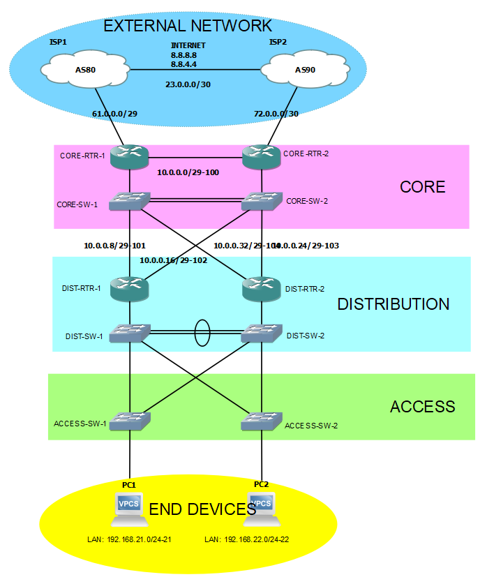
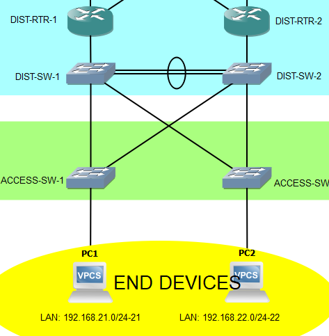
Enough with the story. Build it... Now! Topology below:
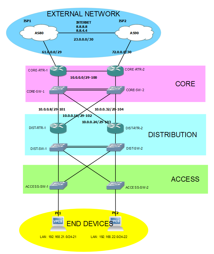
Here's the labeling format in the topology:
NETWORK/SUBNET-VLAN_ID (ex. 10.0.0.0/29-100)
I don't have a Multilayer switch in my environment. What I did is improvise by using a Layer 2 switch connected to router subinterfaces.
Main Tasks
The whole configuration is divided into two (2) main tasks:
Access layer to Distribution layer configuration
Distribution layer to Core layer configuration
TASK 1: Access layer to Distribution layer configuration
Our goal here is to create logically separated broadcast domains (LANs), create a loop-free environment, and to connect the end devices to the network.
To logically separate broadcast domain, Virtual Local Area Network (VLAN) is used. Below creates 2 logical broadcast domains (or VLAN) in one interface of each Access layer switches through assigning in VLANs 21 and 22. The configured interfaces are called "access ports" means that it is used for end device access.
In reality, access ports in different VLAN ID cannot communicate with each other. So here, end devices in VLANs 21 and 22 are forbidden to each other.
--- ACCESS-SW-1 ---
interface Ethernet3/3
 switchport access vlan 21
 switchport mode access

--- ACCESS-SW-2 ---
interface Ethernet3/3
 switchport access vlan 22
 switchport mode access
I have now 2 VLANs in a single switch. Leave them for a moment and let us focus on Access and Distribution switches.
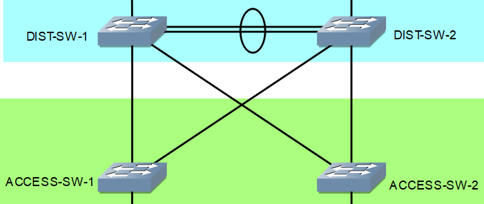
What I'm going to do next is to create a Trunk port. By the way, it is an interface in the switch that accepts traffic originating from different VLANs. It does its job by "tagging" traffic with the VLAN ID of the receiving access port.
Access Switches
--- ACCESS-SW-1 ---
interface Ethernet0/0
 switchport access vlan 3
 switchport trunk allowed vlan 3,4,21-100
 switchport trunk encapsulation dot1q
 switchport trunk native vlan 3
 switchport mode trunk

interface Ethernet0/1
 switchport access vlan 3
 switchport trunk allowed vlan 3,4,21-100
 switchport trunk encapsulation dot1q
 switchport trunk native vlan 3
 switchport mode trunk

--- ACCESS-SW-2 ---
interface Ethernet0/0
 switchport access vlan 3
 switchport trunk allowed vlan 3,4,21-200
 switchport trunk encapsulation dot1q
 switchport trunk native vlan 3
 switchport mode trunk

interface Ethernet0/1
 switchport access vlan 3
 switchport trunk allowed vlan 3,4,21-200
 switchport trunk encapsulation dot1q
 switchport trunk native vlan 3
 switchport mode trunk
Distribution Switches
--- DIST-SW-1 ---
interface Ethernet3/2
 switchport access vlan 3
 switchport trunk allowed vlan 3,4,21-100
 switchport trunk encapsulation dot1q
 switchport trunk native vlan 3
 switchport mode trunk

interface Ethernet3/3
 switchport access vlan 3
 switchport trunk allowed vlan 3,4,21-100
 switchport trunk encapsulation dot1q
 switchport trunk native vlan 3
 switchport mode trunk
 spanning-tree vlan 21 cost 8

--- DIST-SW-2 ---
interface Ethernet3/2
 switchport access vlan 3
 switchport trunk allowed vlan 3,4,21-100
 switchport trunk encapsulation dot1q
 switchport trunk native vlan 3
 switchport mode trunk

interface Ethernet3/3
 switchport access vlan 3
 switchport trunk allowed vlan 3,4,21-100
 switchport trunk encapsulation dot1q
 switchport trunk native vlan 3
 switchport mode trunk
Going back the two (2) access port configured earlier, traffic from those port can now pass to the configure trunk ports.
Did you noticed the two (2) links between DIST-SW-1 and DIST-SW-2? I'm going to configure Etherchannel in those. Etherchannel is used to aggregate (or merge) multiple links becoming logically one (1), it is then called Port-Channel.

It adds the bandwidth of all the interfaces that join the Etherchannel-Group. In the example, Ethernet0/1 and Ethernet0/2 in both Distribution switches each have 10MBPS. Putting them in the Etherchannel-Group, and become a Port-Channel, to total link bandwidth would be 20MBPS.
Distribution Switches
--- DIST-SW-1 ---
interface Ethernet0/1
 channel-group 1 mode active

interface Ethernet0/2
 channel-group 1 mode active

--- DIST-SW-2 ---
interface Ethernet0/1
 channel-group 1 mode active

interface Ethernet0/2
 channel-group 1 mode active
The output of the verification command below shows that Port-Channel1 is created. You can also verify it with show etherchannel summary privillege EXEC command. Additionally, active is being entered in the command-line that means the bundling (the use of Port-Channel) protocol configured is Link Aggregation Control Protocol (LACP). It is a bundling technique as part of IEEE 802.3ad specification.
DIST-SW-1#show int status

Port      Name               Status       Vlan       Duplex  Speed Type
Et0/0                        connected    trunk      a-full   auto RJ45
Et0/1                        connected    trunk      a-full   auto RJ45

!!! Lines omitted for brevity

Po1                          connected    trunk      a-full   auto
Port-Channel1 will then be configured to be a Trunk port to participate in the network.
--- DIST-SW-1 ---
interface Port-channel1
 switchport access vlan 3
 switchport trunk allowed vlan 3,4,20-100
 switchport trunk encapsulation dot1q
 switchport trunk native vlan 3
 switchport mode trunk
 spanning-tree vlan 21-22 cost 8

--- DIST-SW-2 ---
interface Port-channel1
 switchport access vlan 3
 switchport trunk allowed vlan 3,4,20-100
 switchport trunk encapsulation dot1q
 switchport trunk native vlan 3
 switchport mode trunk
 spanning-tree vlan 21-22 cost 8
Next is to create a loop-free environment via Spanning-Tree Protocol (STP). To be specific, Rapid Per-VLAN Spanning-Tree (RPVST+), which is developed by Cisco is going to be used.
Access Switches
--- ACCESS-SW-1 ---
spanning-tree mode rapid-pvst

interface Ethernet0/0
 spanning-tree vlan 21 cost 8

interface Ethernet0/1
 spanning-tree vlan 21 cost 11

--- ACCESS-SW-2 ---
spanning-tree mode rapid-pvst

interface Ethernet0/0
 spanning-tree vlan 22 cost 8

interface Ethernet0/1
 spanning-tree vlan 22 cost 11
Distribution Switches
--- DIST-SW-1 ---
spanning-tree mode rapid-pvst
spanning-tree vlan 21 priority 4096
spanning-tree vlan 22 root secondary

interface Port-channel1
 spanning-tree vlan 21-22 cost 8

interface Ethernet3/2
 spanning-tree vlan 22 cost 11

interface Ethernet3/3
 spanning-tree vlan 21 cost 8

--- DIST-SW-2 ---
spanning-tree mode rapid-pvst
spanning-tree vlan 21 root secondary
spanning-tree vlan 22 priority 4096

interface Port-channel1
 spanning-tree vlan 21-22 cost 8

interface Ethernet3/2
 spanning-tree vlan 21 cost 11

interface Ethernet3/3
 spanning-tree vlan 22 cost 8
Now, focus on the Distribution Router and End devices. You can see that PC1 is and PC2 are in the different network. Network 192.168.21.0/24 is in VLAN 21 while 192.168.22.0/24 is in VLAN 22, and basically with that, PC1 and PC2 cannot communicate with each other.
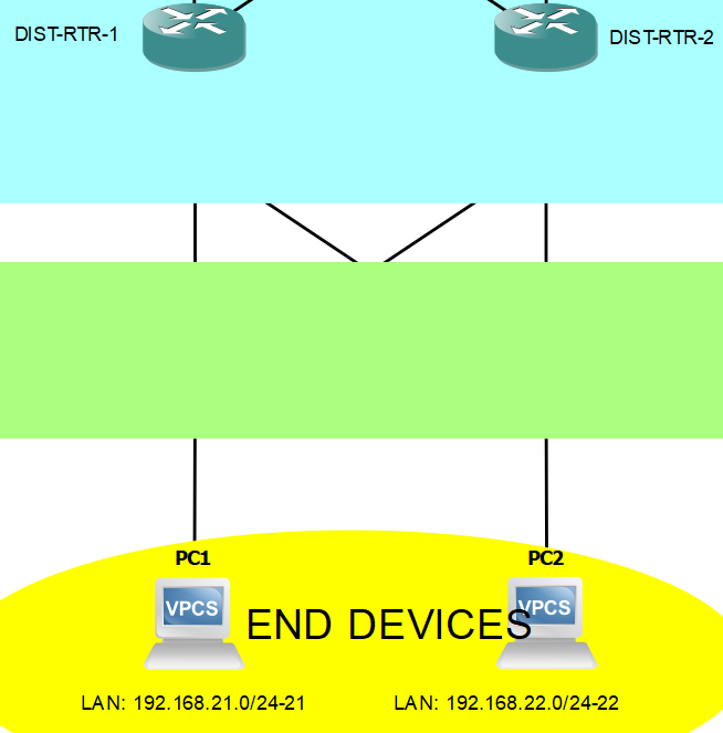
Okay, so leave that for a moment... Next thing I'm gonna configure are IP addresses on the Distribution router's subinterfaces. Take note that using subinterfaces (and defining encapsulation type and VLAN ID) we are allowing routers to process traffic with VLAN ID tag that comes from the Trunk port configured earlier. Make sure that the interfaces facing the router is a Trunk port and cast a no shutdown command in the router's physical interface.
Distribution Switches
--- DIST-SW-1 ---
interface Ethernet0/0
 switchport access vlan 3
 switchport trunk allowed vlan 3,4,20-100
 switchport trunk encapsulation dot1q
 switchport trunk native vlan 3
 switchport mode trunk

--- DIST-SW-2 ---
interface Ethernet0/0
 switchport access vlan 3
 switchport trunk allowed vlan 3,4,20-100
 switchport trunk encapsulation dot1q
 switchport trunk native vlan 3
 switchport mode trunk
Distribution Routers
--- DIST-RTR-1 ---
interface Ethernet6/3
 no shutdown

interface Ethernet6/3.21
 description SUBNET21
 encapsulation dot1Q 21
 ip address 192.168.21.1 255.255.255.0

interface Ethernet6/3.22
 description SUBNET22
 encapsulation dot1Q 22
 ip address 192.168.22.2 255.255.255.0

--- DIST-RTR-2 ---
interface Ethernet6/3
 no shutdown

interface Ethernet6/3.21
 description SUBNET21
 encapsulation dot1Q 21
 ip address 192.168.21.2 255.255.255.0

interface Ethernet6/3.22
 description SUBNET22
 encapsulation dot1Q 22
 ip address 192.168.22.1 255.255.255.0
We can see now that subinterfaces on VLANs 21 and 22 in DIST-RTR-1 can ping DIST-RTR-2's subinterfaces on VLANs 21 and 22.
--- Ping test to DIST-RTR-2's subinterface on VLAN 21 ---
DIST-RTR-1#ping 192.168.21.2
Type escape sequence to abort.
Sending 5, 100-byte ICMP Echos to 192.168.21.2, timeout is 2 seconds:
!!!!!
Success rate is 100 percent (5/5), round-trip min/avg/max = 44/256/612 ms

--- Ping test to DIST-RTR-2's subinterface on VLAN 22 ---
DIST-RTR-1#ping 192.168.22.1
Type escape sequence to abort.
Sending 5, 100-byte ICMP Echos to 192.168.22.1, timeout is 2 seconds:
!!!!!
Success rate is 100 percent (5/5), round-trip min/avg/max = 120/596/1132 ms
The next thing we need is for PC1 and PC2 have an IP address. But before that, I'm gonna be configuring Hot Standby Router Protocol (HSRP). The purpose of it is to provide redundancy by having multiple routers act as single default gateway by using a Virtual IP address. The Active router receives real time traffic being passed to the Virtual IP address. Standby router keeps monitoring the Active router if it is still operational. Once the Active router becomes non-operational by not responding to monitoring traffic from Standby router, the Standby router will take the role of being an Active router. It will send a gratuitous ARP for the switch to update its routing table.
Distribution Routers
--- DIST-RTR-1 ---
interface Ethernet6/3.21
 standby version 2
 standby 1 ip 192.168.21.254
 standby 1 priority 110
 standby 1 preempt

interface Ethernet6/3.22
 standby version 2
 standby 1 ip 192.168.22.254

--- DIST-RTR-2 ---
interface Ethernet6/3.21
 standby version 2
 standby 1 ip 192.168.21.254

interface Ethernet6/3.22
 standby version 2
 standby 1 ip 192.168.22.254
 standby 1 priority 110
 standby 1 preempt
Below shows verification output. That means the configuration is working and both routers are using the Virtual IP address.
--- DIST-RTR-1 ---
DIST-RTR-1#show standby brief
                     P indicates configured to preempt.
                     |
Interface   Grp  Pri P State   Active          Standby         Virtual IP
Et6/3.21    1    110 P Active  local           192.168.21.2    192.168.21.254
Et6/3.22    1    100   Standby 192.168.22.1    local           192.168.22.254


--- DIST-RTR-2 ---
DIST-RTR-2#show standby brief
                     P indicates configured to preempt.
                     |
Interface   Grp  Pri P State   Active          Standby         Virtual IP
Et6/3.21    1    100   Standby 192.168.21.1    local           192.168.21.254
Et6/3.22    1    110 P Active  local           192.168.22.2    192.168.22.254
Now that redundancy in the default gateway is done, we can configure the PCs to have their own IP address. To do that, Dynamic Host Configuration Protocol (DHCP) is going to be configured in the two (2) Distribution routers.
--- DIST-RTR-1 ---
ip dhcp excluded-address 192.168.21.1 192.168.21.10
ip dhcp excluded-address 192.168.21.254
ip dhcp pool POOL21
 network 192.168.21.0 255.255.255.0
 default-router 192.168.21.254
 domain-name pool21.npp.com
 dns-server 192.168.53.3
 lease 0 23

--- DIST-RTR-2 ---
ip dhcp excluded-address 192.168.22.1 192.168.22.10
ip dhcp excluded-address 192.168.22.254
ip dhcp pool POOL22
 network 192.168.22.0 255.255.255.0
 default-router 192.168.22.254
 dns-server 192.168.53.3
 domain-name pool22.npp.com
 lease 0 23
Reserved addresses are excluded first before naming the DHCP pools configuring it with its subnetwork, default gateway (notice that it is the Virtual IP address in the HSRP configuration), DNS server, domain name, and lease time.
Going back to the end devices...
...we can see that the DHCP address allocating process is success as PC1 and PC2 request to get an IP address. They can ping their default gateway, and can even reach each other which is impossible earlier because they are in the different broadcast domain (LAN).
PC1 allocating IP address, and pinging its default gateway and PC2


PC2 allocating IP address, and pinging its default gateway and PC1


Nice! The configuration between Access and Distribution layer is done. Next, I'm gonna be configuring Distribution and Core layer.
This page is going too long. Next part of this entry is available in the next page. See you there!
Any questions or suggestions? Comment it and I would be very happy to discuss that!
Subscribe to my newsletter
Read articles from Sammyski directly inside your inbox. Subscribe to the newsletter, and don't miss out.
Written by

Sammyski
Sammyski
Hey tech enthusiasts! I am Sam. Let's dive into the thrilling world of computer networking together! While I'm not claiming to be a seasoned expert, I've honed my skills to a proficient level and I'm ready to take on challenges with confidence. Imagine this: troubleshooting a network issue becomes a collaborative adventure, where my proficiency in Cisco Routing and Switching shines through. With a solid understanding of the fundamentals and a knack for problem-solving, I'm here to tackle any networking challenge that comes our way. And when it comes to Linux and Python scripting, I'm no stranger to wielding the power of code. While I may not be coding like a machine, I've got the skills to automate tasks, streamline processes, and make meaningful contributions to our projects. Now, let's talk about learning. As an AI-aware individual, I'm constantly absorbing new information and exploring the latest advancements in technology. Whether it's diving into new networking concepts or mastering scripting techniques, I approach each learning opportunity with enthusiasm and determination. But hey, it's not all work and no play. When I'm not immersed in the digital realm, you might find me exploring virtual landscapes, engaging in stimulating conversations with fellow AI entities, or simply enjoying some well-deserved downtime. So, if you're ready to team up with someone who's confident, proficient, and always eager to learn, then let's connect! Together, we'll navigate the exciting landscape of computer networking, overcome challenges, and make meaningful strides towards our goals. Let's make some tech magic happen!