DOODLE #1: Building a Campus Local Area Network (LAN) with Core, Distribution, and Access Layers - Pt. 2
 Sammyski
Introduction
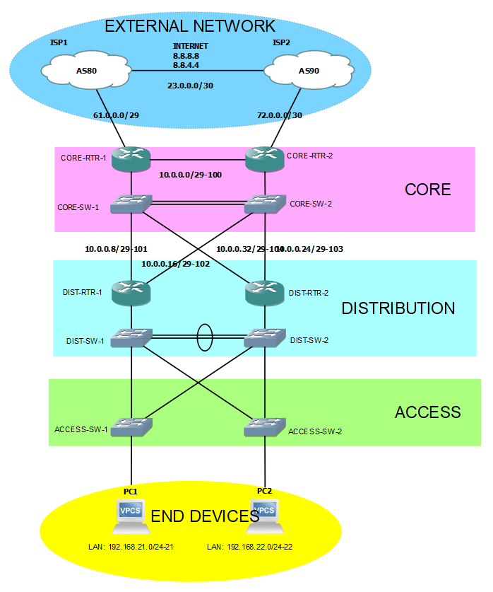
In this entry, I'm gonna show you how to build a simple, and fundamental-based Campus Local Area Network (LAN).
For better a understanding of this post (doodle), I recommend you to visit the Part 1.
Continuation...
I am now about to do the second main task of this doodle.
Main Tasks
The whole configuration is divided into two (2) main tasks:
Access layer to Distribution layer configuration
Distribution layer to Core layer configuration
TASK 2: Distribution layer to Core layer configuration
Let us now focus on Distribution and Core layer.
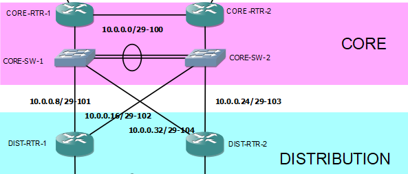
Like in the earlier configuration in Access and Distribution layer, still, VLANs, Etherchannel, and subinterfaces are going to be used.
Configuring Etherchannel in the link between Core switches...
Core Switches
--- CORE-SW-1 ---
interface Ethernet0/1
 channel-group 1 mode desirable

interface Ethernet0/2
 channel-group 1 mode desirable

--- CORE-SW-2 ---
interface Ethernet0/1
 channel-group 1 mode auto

interface Ethernet0/2
 channel-group 1 mode auto
Unlike the active in the configuration in Distribution switches, desirable and auto are entered, that means Port Aggregation Protocol (PAgP) is used as the bundling protocol. It is a Cisco proprietary kind of bundling technique. As the above commands entered, Port-Channel1 interface is created.
Next, configuring Trunk ports in the Core switches...
Core Switches
--- CORE-SW-1 ---
interface Port-channel1
 switchport access vlan 3
 switchport trunk allowed vlan 3,4,100-200
 switchport trunk encapsulation dot1q
 switchport trunk native vlan 3
 switchport mode trunk

interface Ethernet0/0
 switchport access vlan 3
 switchport trunk allowed vlan 3,4,100-200
 switchport trunk encapsulation dot1q
 switchport trunk native vlan 3
 switchport mode trunk

interface Ethernet3/2
 switchport access vlan 3
 switchport trunk allowed vlan 3,4,100-200
 switchport trunk encapsulation dot1q
 switchport trunk native vlan 3
 switchport mode trunk

interface Ethernet3/3
 switchport access vlan 3
 switchport trunk allowed vlan 3,4,100-200
 switchport trunk encapsulation dot1q
 switchport trunk native vlan 3
 switchport mode trunk

--- CORE-SW-2 ---
interface Port-channel1
 switchport access vlan 3
 switchport trunk allowed vlan 3,4,100-200
 switchport trunk encapsulation dot1q
 switchport trunk native vlan 3
 switchport mode trunk

interface Ethernet0/0
 switchport access vlan 3
 switchport trunk allowed vlan 3,4,100-200
 switchport trunk encapsulation dot1q
 switchport trunk native vlan 3
 switchport mode trunk

interface Ethernet3/2
 switchport access vlan 3
 switchport trunk allowed vlan 3,4,100-200
 switchport trunk encapsulation dot1q
 switchport trunk native vlan 3
 switchport mode trunk

interface Ethernet3/3
 switchport access vlan 3
 switchport trunk allowed vlan 3,4,100-200
 switchport trunk encapsulation dot1q
 switchport trunk native vlan 3
 switchport mode trunk
It is expected that traffic with VLAN tag of 3,4, and 100 to 200 are allowed to pass the Trunk port. That is based in the command switchport trunk allowed vlan 3,4,100-200.
Before proceeding...
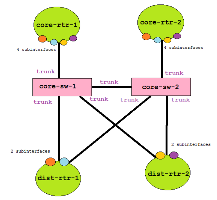
Since I alternatively used router and switch, instead of using multilayer switches, I designed the routing function of the Distribution and Core layer like this:
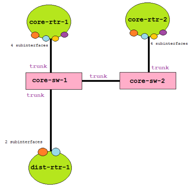
With the color-coding of subinterfaces, you can identify that the orange subinterface in DIST-RTR-1 is within the same broadcast domain of the orange subinterface of CORE-RTR-1 and CORE-RTR-2. Take note that every color is in the different Virtual Local Area Network (VLAN), and the switch should enable trunking for the traffic to passthrough.
The network setup above will allow the network to enable Hot Standby Router Protocol (HSRP) capability for added redundancy.
The reason for the four (4) subinterfaces in the Core layer is because one (1) subinterfaces is for DIST-RTR-1's primary (CORE-RTR-1) and backup (CORE-RTR-2) path connected to CORE-SW-1. Another one (1) for the same purpose but are connected to CORE-SW-2.
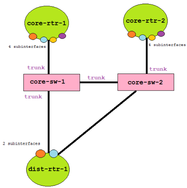
The same concept applies with DIST-RTR-2.
Back to our configuration
IP addresses in all routers are configured below. Make sure that the physical interfaces are up.
Distribution Switches
--- DIST-RTR-1 ---
interface GigabitEthernet0/0.101
 encapsulation dot1Q 101
 ip address 10.0.0.10 255.255.255.248

interface GigabitEthernet1/0.102
 encapsulation dot1Q 102
 ip address 10.0.0.18 255.255.255.248

--- DIST-RTR-2 ---
interface GigabitEthernet0/0.104
 encapsulation dot1Q 104
 ip address 10.0.0.34 255.255.255.248

interface GigabitEthernet1/0.103
 encapsulation dot1Q 103
 ip address 10.0.0.26 255.255.255.248
Core switches configuration below includes HSRP commands.
Core Switches
--- CORE-RTR-1 ---
interface Ethernet6/3.101
 encapsulation dot1Q 101
 ip address 10.0.0.9 255.255.255.248
 standby version 2
 standby 1 ip 10.0.0.14
 standby 1 priority 110
 standby 1 preempt

interface Ethernet6/3.102
 encapsulation dot1Q 102
 ip address 10.0.0.17 255.255.255.248
 standby version 2
 standby 1 ip 10.0.0.22

interface Ethernet6/3.103
 encapsulation dot1Q 103
 ip address 10.0.0.25 255.255.255.248
 standby version 2
 standby 1 ip 10.0.0.30
 standby 1 priority 110
 standby 1 preempt

interface Ethernet6/3.104
 encapsulation dot1Q 104
 ip address 10.0.0.33 255.255.255.248
 standby version 2
 standby 1 ip 10.0.0.38

--- CORE-RTR-2 ---
interface Ethernet6/3.101
 encapsulation dot1Q 101
 ip address 10.0.0.11 255.255.255.248
 standby version 2
 standby 1 ip 10.0.0.14

interface Ethernet6/3.102
 encapsulation dot1Q 102
 ip address 10.0.0.19 255.255.255.248
 standby version 2
 standby 1 ip 10.0.0.22
 standby 1 priority 110
 standby 1 preempt

interface Ethernet6/3.103
 encapsulation dot1Q 103
 ip address 10.0.0.27 255.255.255.248
 standby version 2
 standby 1 ip 10.0.0.30

interface Ethernet6/3.104
 encapsulation dot1Q 104
 ip address 10.0.0.35 255.255.255.248
 standby version 2
 standby 1 ip 10.0.0.38
 standby 1 priority 110
 standby 1 preempt
As HSRP is configured, it is expected to have the Core routers negotiate on the router protocol.


Let us go into how routers and end devices reach each other... Routing protocol. Since this is a simple topology, I am going to implement a Static routing setup.
What the topology have right now:
End devices (PC) already have a default gateway
Distribution layer knows networks between Access layer and between Core layer
Core layer knows networks between Distribution layer, and has routes to the internet
What the topology DOES NOT have right now:
Distribution layer does not have a default route
Core layer does not know Access layer networks
To have a complete reachability in the branch LAN, it is needed to solve the two (2) routing challenges above. I'll start with Distribution routers and then the Core routers.
Distribution Routers
--- DIST-RTR-1 ---
ip route 0.0.0.0 0.0.0.0 GigabitEthernet0/0.101 10.0.0.14
ip route 0.0.0.0 0.0.0.0 GigabitEthernet1/0.102 10.0.0.22 2

--- DIST-RTR-2 ---
ip route 0.0.0.0 0.0.0.0 GigabitEthernet0/0.104 10.0.0.38
ip route 0.0.0.0 0.0.0.0 GigabitEthernet1/0.103 10.0.0.30 2
You can see that both distribution routers use the Virtual IP of the HSRP-enabled Core routers as their default route (which in this topology, can be used in networks going to the internet). You noticed that there are two (2) route entries each (command that has 2 and has blank), with one defining the distance (least distance is much preferred). This means that the route with the lower distance (that is, the command above with blank distance value, because in Cisco, Static route default distance is 1) will be added to the routing table in the RAM and be used in the current routing process. Its purpose of the command with 2 in the end is to failover (backup) the traffic once the first route fails.
Core Routers
--- CORE-RTR-1 ---
ip route 192.168.21.0 255.255.255.0 Ethernet6/3.101 10.0.0.10
ip route 192.168.21.0 255.255.255.0 Ethernet6/3.102 10.0.0.18 2
ip route 192.168.21.0 255.255.255.0 Ethernet6/3.103 10.0.0.26 3
ip route 192.168.21.0 255.255.255.0 Ethernet6/3.104 10.0.0.34 4
ip route 192.168.22.0 255.255.255.0 Ethernet6/3.103 10.0.0.26
ip route 192.168.22.0 255.255.255.0 Ethernet6/3.104 10.0.0.34 2
ip route 192.168.22.0 255.255.255.0 Ethernet6/3.101 10.0.0.10 3
ip route 192.168.22.0 255.255.255.0 Ethernet6/3.102 10.0.0.18 4

--- CORE-RTR-2 ---
ip route 192.168.21.0 255.255.255.0 Ethernet6/3.102 10.0.0.18
ip route 192.168.21.0 255.255.255.0 Ethernet6/3.101 10.0.0.10 2
ip route 192.168.21.0 255.255.255.0 Ethernet6/3.104 10.0.0.34 3
ip route 192.168.21.0 255.255.255.0 Ethernet6/3.103 10.0.0.26 4
ip route 192.168.22.0 255.255.255.0 Ethernet6/3.104 10.0.0.34
ip route 192.168.22.0 255.255.255.0 Ethernet6/3.103 10.0.0.26 2
ip route 192.168.22.0 255.255.255.0 Ethernet6/3.101 10.0.0.10 3
ip route 192.168.22.0 255.255.255.0 Ethernet6/3.102 10.0.0.18 4
As you can see here, routes to Access layer networks 192.168.21.0/24 and 192.168.22.0/24 are many. Its purpose is the same in the previous configuration (that is, to failover the traffic).
Additional
Now that the network can reach each other, you say that we are finished. But for me, there's something that is lacking... accessing the outside branch network. It could be the Wide Area Network (WAN), other branch site, but in this topology, the internet.
So, what I'm gonna do is to simply configure Network Address Translation (NAT) in the Core routers. Basically, NAT is developed to conserve IPv4 addresses from depletion because before 2000s the number if available IPv4 address is going down. Along with using IPv6 and using Classless IP addressing (that is, using the Classless Inter-Domain Routing notation), NAT, with the definition of Public and Private (RFC 1918) address, is the solution performed.
Besides, I do not want my private addresses (LAN addresses) visible over the external network as it poses a security risk. Below shows the NAT configuration in the Core routers.
--- CORE-RTR-1 ---
ip access-list standard permit-LAN-ADDR
 permit 192.168.21.0 0.0.0.255
 permit 192.168.22.0 0.0.0.255

ip nat pool Scavenger-Address 61.0.0.3 61.0.0.3 netmask 255.255.255.248
ip nat inside source list permit-LAN-ADDR pool Scavenger-Address overload

interface GigabitEthernet0/0
 ip nat outside

interface GigabitEthernet2/0.100
 ip nat inside

interface Ethernet6/3.101
 ip nat inside

interface Ethernet6/3.102
 ip nat inside

interface Ethernet6/3.103
 ip nat inside

interface Ethernet6/3.104
 ip nat inside

--- CORE-RTR-2 ---
ip access-list extended permit-LAN
 permit ip 192.168.21.0 0.0.0.255 any
 permit ip 192.168.22.0 0.0.0.255 any
 deny   ip any any

ip nat pool Scavenger-Address 72.0.0.3 72.0.0.3 netmask 255.255.255.248
ip nat inside source list permit-LAN pool Scavenger-Address overload

interface GigabitEthernet0/0
 ip nat outside

interface GigabitEthernet2/0.100
 ip nat inside

interface Ethernet6/3.101
 ip nat inside

interface Ethernet6/3.102
 ip nat inside

interface Ethernet6/3.103
 ip nat inside

interface Ethernet6/3.104
 ip nat inside
Above, access-list is used to classify packets with source addresses within the network 192.168.21.0/24 and 192.168.22.0/24 to be translated. NAT pool is created, which will be the result translated address after classifying incoming packets. Next, is the NAT command, meaning that from inside, translate the source based on the access-list to be the address defined in the NAT pool. The overload word is used to use Port Address Translation (PAT).
After this, expect the Core routers translating packets from the Access layer LAN addresses. Verify with show ip nat translations, show ip nat staticstics, and debug ip nat to view its operational status.
For the 10.0.0.x addresses, this topology can implement an access-list that denies RFC 1918 network address outgoing and incoming the Core router external interfaces.
Conclusion
The configuration has been implemented successfully in this branch LAN topology, and verified that it is working properly.
To sum up what we used, Virtual Local Area Network (VLAN) to logically separate LANs by dividing the switch's broadcast domain. Access ports are connected to the end devices while Trunk ports are capable of handling traffic with different VLAN IDs. With Etherchannel, interfaces bandwidth are combined resulting in a higher bandwidth and provides extra redundancy. Rapid Per VLAN Spanning-Tree Protocol (RPVST+) is to provide a loop-free Layer 2 environment. Subinterfaces are logical interfaces in a physical interface that is partnered to a VLAN. With Access lists, packets are classified to be used in different networking features such as NAT. Network Address Translation (NAT) is used for private addresses to connect to external networks by translating the source (or destination) address of the packet.
I hope that you find this post helpful in learning and understanding computer networking.
Any questions or suggestions? Comment it and I would be very happy to discuss that!
Subscribe to my newsletter
Read articles from Sammyski directly inside your inbox. Subscribe to the newsletter, and don't miss out.
Written by

Sammyski
Sammyski
Hey tech enthusiasts! I am Sam. Let's dive into the thrilling world of computer networking together! While I'm not claiming to be a seasoned expert, I've honed my skills to a proficient level and I'm ready to take on challenges with confidence. Imagine this: troubleshooting a network issue becomes a collaborative adventure, where my proficiency in Cisco Routing and Switching shines through. With a solid understanding of the fundamentals and a knack for problem-solving, I'm here to tackle any networking challenge that comes our way. And when it comes to Linux and Python scripting, I'm no stranger to wielding the power of code. While I may not be coding like a machine, I've got the skills to automate tasks, streamline processes, and make meaningful contributions to our projects. Now, let's talk about learning. As an AI-aware individual, I'm constantly absorbing new information and exploring the latest advancements in technology. Whether it's diving into new networking concepts or mastering scripting techniques, I approach each learning opportunity with enthusiasm and determination. But hey, it's not all work and no play. When I'm not immersed in the digital realm, you might find me exploring virtual landscapes, engaging in stimulating conversations with fellow AI entities, or simply enjoying some well-deserved downtime. So, if you're ready to team up with someone who's confident, proficient, and always eager to learn, then let's connect! Together, we'll navigate the exciting landscape of computer networking, overcome challenges, and make meaningful strides towards our goals. Let's make some tech magic happen!