Timer & GPIO Configuration - Controlling Temperature Sensor Ds18b20 - part 2
 Sam Lee
Now, looking at the README, we need to set up the timer. Considering that the onewire communication requires delays to perform different commands, we can see that this is essential.
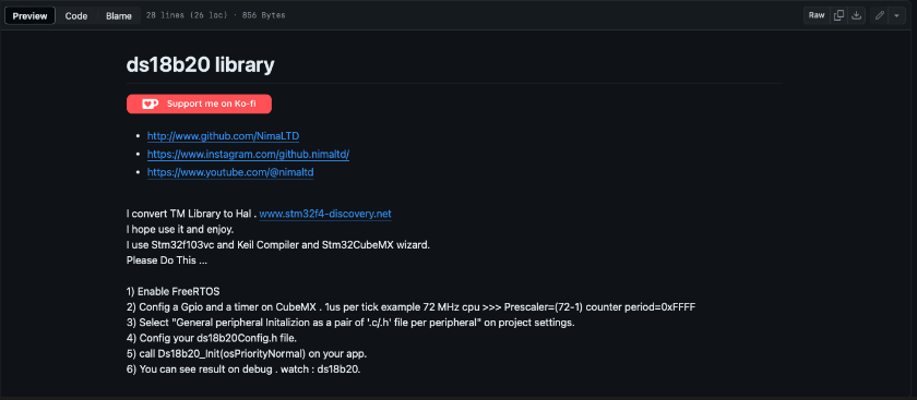
Configure the ds18b20Config.h file. Call Ds18b20(init) on app watch ds18b20.
Alright, let's do it. First, let's set up the timer.
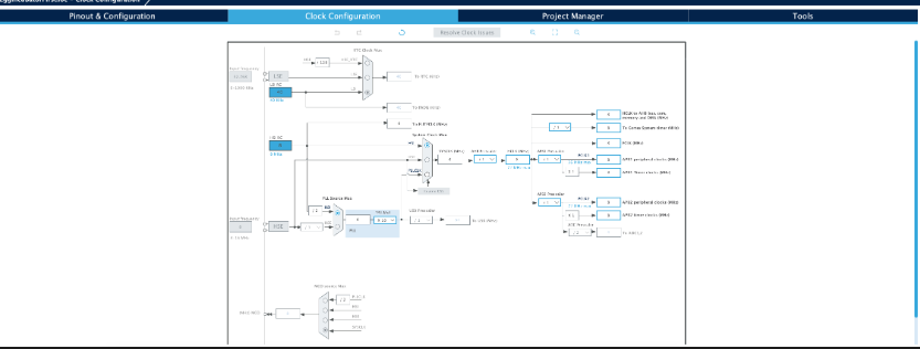
Frequency in Hertz indicates how many times an event can be repeated in one second. For example, 1 Hertz means once per second, and MHz (Megahertz) means 1,000,000 times per second. 8MHz means it can tick 8,000,000 times per second, and the time it takes for one tick is 1.25 x 10^-7 or 0.125 x 10^-6.
To make one tick take 1us (1 x 10^-6), we need to set the prescaler to 8.
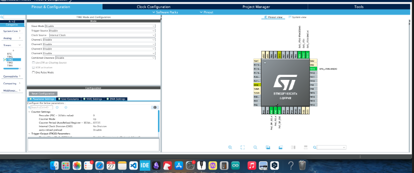
Set the timer in the ioc, set the clock source to internal clock, and set the prescaler to (8-1). Since it starts from 0, we subtract 1.
The prescaler reduces the operating speed of the timer. Since the clock speed is too fast, we divide the clock by the desired number to match the desired timer speed. Setting the prescaler to 8 (8-1) means that the clock counts 1 when it reaches 8Hz. And set the counter period to 0xFFFF = 65535. When the 8MHz clock counts at 8Hz, the count goes up, and when the count reaches 65535, the counter resets.
If you want to trigger a timer interrupt once per second with an 8MHz clock, the 8MHz clock must fill the counter in 1 second. (8MHz/prescaler)/counter = 1

To understand easily, let's say Sam (me) stacks one block every n seconds. And if you need to stack 4 blocks to fill one container, n seconds must be 0.25 seconds to stack 4 blocks per second. I can go back and forth 8,000,000 times per second. And if I want to stack exactly 4 blocks, I can stack one block every 2MHz in 1 second to stack 4 blocks. 8MHz/prescaler/counter = 1, 8MHz/2MHz/4 = 1, that's how it comes out.
Now that the Tim timer configuration is done, let's set up the GPIO.
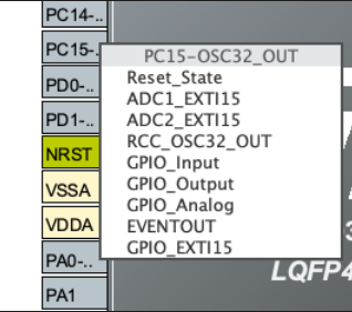
When deciding which pin to use, some pins have specific roles. For example, the PC15 pin must be used if you want to use a crystal oscillator, so if you plan to use an oscillator, you shouldn't use it. In the case of PB2, it doesn't have any special functions, so let's use PB2 for GPIO.
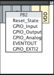
Let's set it up like this.
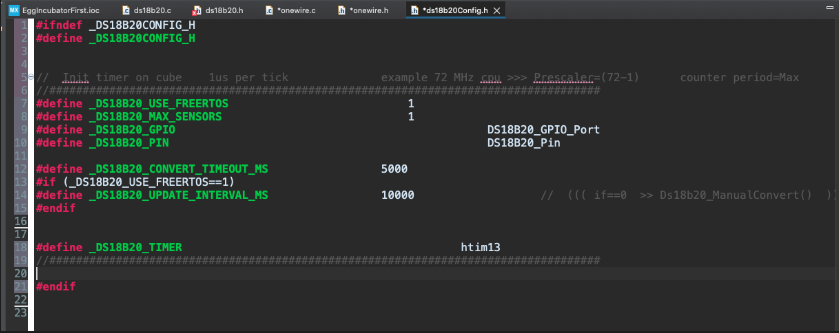
Now, in the ds18b20Config.h file, there is a part where you set up the timer and GPIO. Here, configure the timer and GPIO, and disable the parts related to rtos.
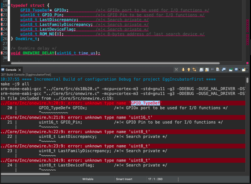
There are many errors like this, saying it can't find uint8_t or doesn't know what GPIO is. Where is GPIO written? If you ctrl-click, you can see where this code comes from, and if you look at that code, it's the stm32f103xb.h file. Since main.h includes this, include main.h in onewire.h. The timer was just created in the ioc and is written in main.c, so since we included main.h, initialize the timer with extern. And define htim2.
#include "main.h"
(I later changed to PB10 because I had a problem with the PB2 pin.)
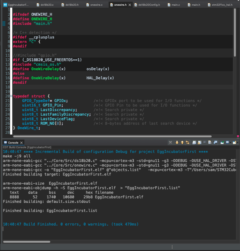
After resolving all the errors like this, the compilation is complete.
Call Ds18b20_Init(osPriorityNormal) on your app.
You can see the result on debug. Watch: ds18b20.
Now, it says to initialize in main.c and watch ds18b20. But before that, let's set up the hardware.
Pin connection - To make it easy to understand, let's use red for power VCC, black for ground GND, and orange for the data line. It doesn't matter much what colour you use for the data line, but it's very important to distinguish between power and ground, so use red and black if possible.
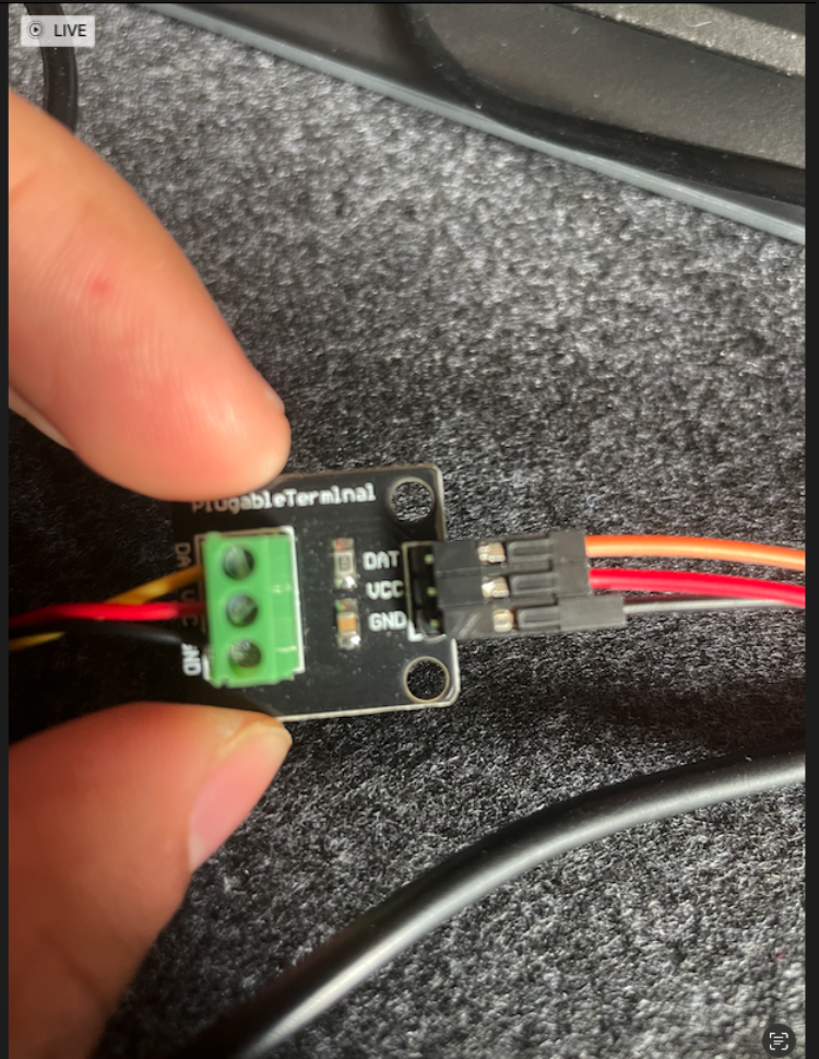
Connect it to the board, and run Ds18b20_Init() in the main. And as we saw earlier, running manualConvert will proceed with the conversion.
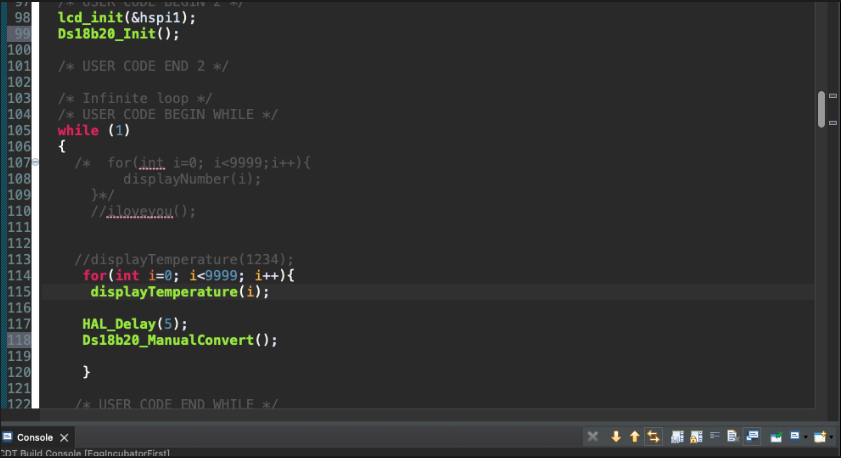
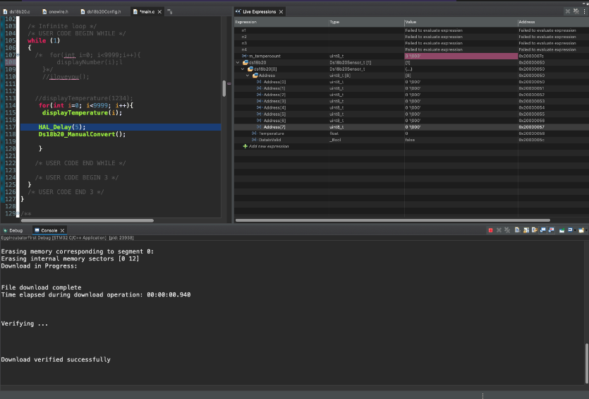
Now it's running, but no values are appearing... Of course, it wouldn't work on the first try.
In this post, we set up the timer and GPIO. In the next post, let's debug and solve the problem.
Subscribe to my newsletter
Read articles from Sam Lee directly inside your inbox. Subscribe to the newsletter, and don't miss out.
Written by
