Debugging -2 : Controlling Temperature Sensor Ds18b20 - part 4
 Sam Lee
In the previous post, we examined the GPIO settings.
The address for GPIO is 0x400010c00, and the pin is 1024.
Is 0x400010c00 indeed PB, and is 1024 the position for PB10?
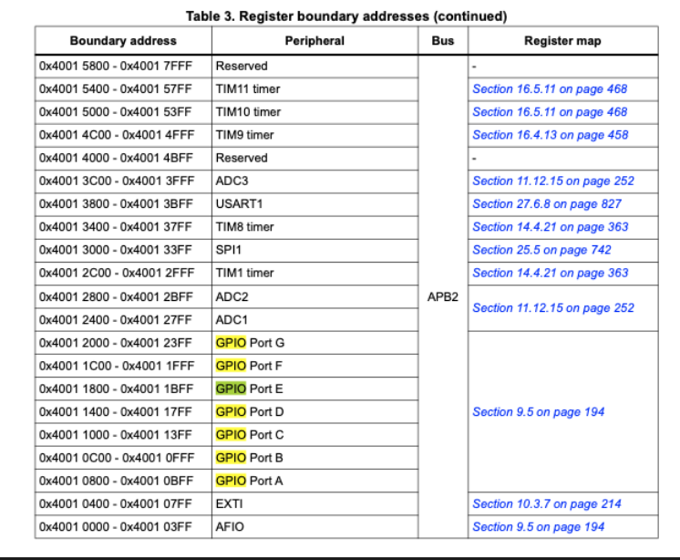
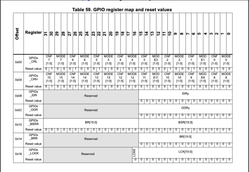
Found it.
GPIO B is indeed 0x4001 0C00. 1024 is 0100 0000 0000, which means it's the 11th pin. Since we start counting from 0, the 11th digit is the 10th pin.
Ah.
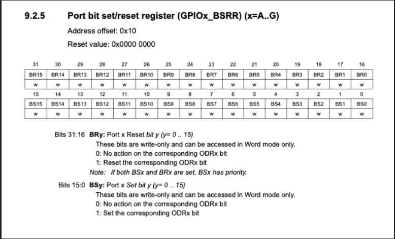
While looking at the datasheet, I found out that BSRR is write-only and cannot be read. I spent hours testing and wondering why the BSRR value wasn't changing, only to find out it's write-only. How disappointing.
So, how do we know if we wrote the value correctly to BSRR?
Since it changes the ODR bits, we can read the ODR bits.
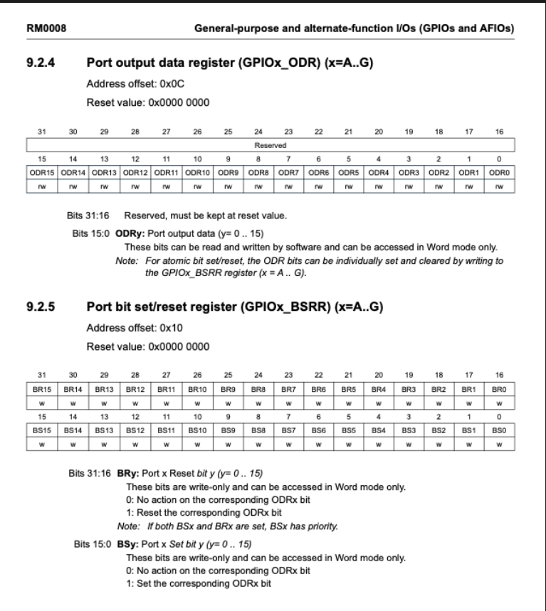
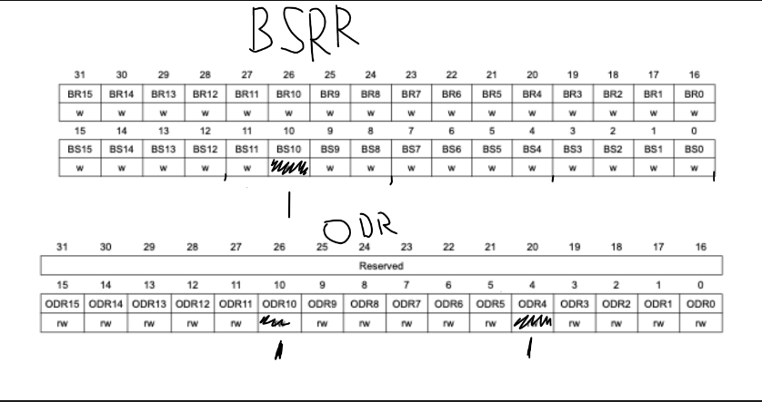
As you can see, ODR uses only bits 0-15, and bits 16-31 are unused.
BSRR controls the ODR bits.
BR stands for Bit Reset, and BS stands for Bit Set.
If the value is 0, no action is taken. If the value is 1, a Set/Reset action occurs.
In the case of (BS == 1 && BR == 1), BS has priority.
Now, let's examine the current operation.
BSRR is a write-only pin, and the value of GPIO_Pin is 1024 because it's PB10.
So,
For ONEWIRE_HIGH, BSRR = 1024, and for ONEWIRE_LOW, BSRR = 1024 << 16.
What is the ODR value for ONEWIRE_HIGH?
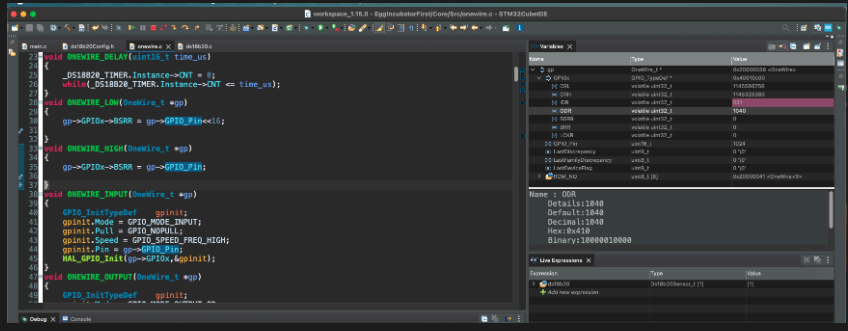
It's 1040.
What is the ODR value for ONEWIRE_LOW?

It's 16.
This should be the state when it's HIGH, so why is bit 4 in ODR turned on? Why is it 1040 instead of 1024?
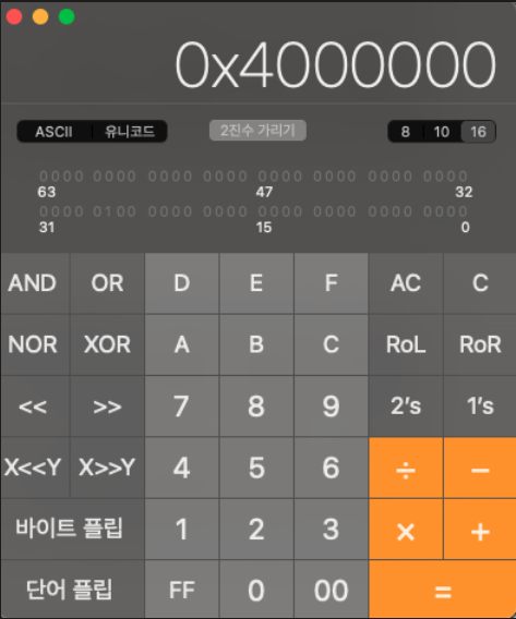
And 1024 << 16 is 0x400000.
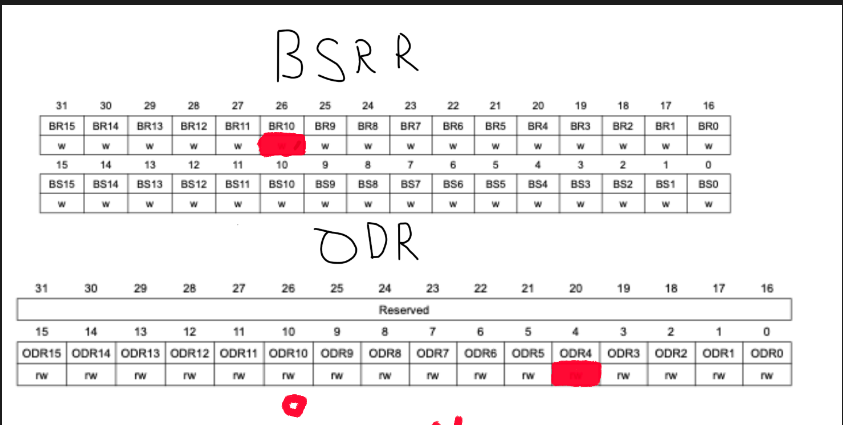
It makes sense.
Since the 26th bit is set, the 10th bit is reset.
So, originally it was 1040, but subtracting 1024 leaves 16.
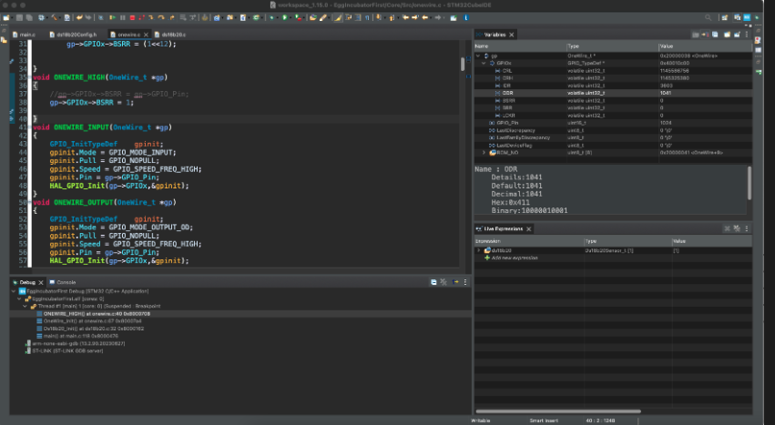
Just to check, I wrote 1, and the value became 1041. This suggests that 1040 might be the default value.
It seems like the BSRR is performing an OR operation with the default value.
So, 1040 BSRR works like this.
If we do 1040 | 1024, the result is obviously 1040.
And since we did 1040 | 1, the result is 1041.
There might have been a previous BSRR operation with 16.
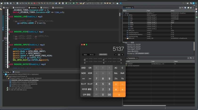
Then, in ONEWIRE_LOW, BSRR = 1 << 12, so the 12th bit is set, and the rest remains 1041.
So, it seems there is no issue with the OneWire HIGH and LOW functions.

This means there is no issue with the initialization.
So, we have confirmed that there is no issue with the OneWire HIGH and LOW functions, and it seems there is no issue with the OneWire Init either.
Therefore, the GPIO settings seem to be fine.
The main issue seems to be that the OneWire protocol changes commands based on the delay, so is the correct delay being applied? Is the clock set correctly?
The README says - Configure a GPIO and a timer on CubeMX. 1us per tick example 72 MHz CPU >>> Prescaler=(72-1) counter period=0xFFFF
Should we try changing the clock to 72MHz?
Currently, the clock cannot be set to 72MHz. To increase the clock, we need to use a crystal oscillator.
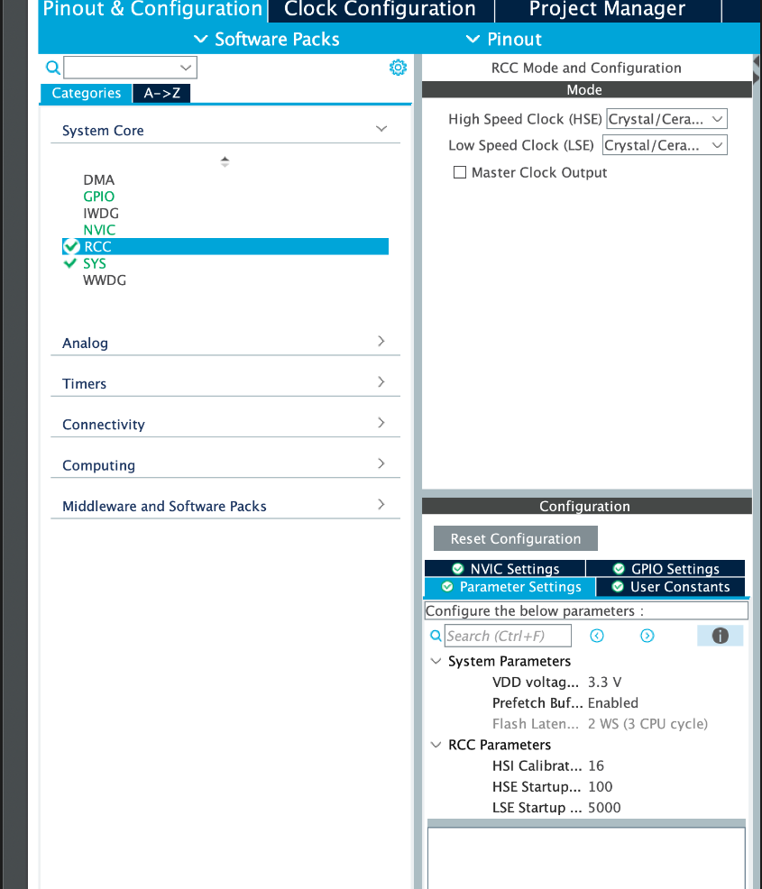
Using a crystal oscillator allows us to set the clock to 72MHz.
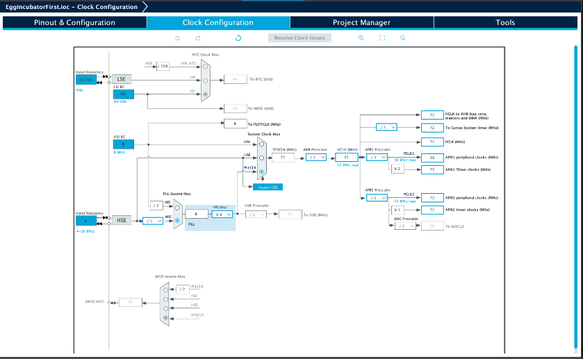
Then, go to the timer and set the prescaler to 71 and the counter to the maximum value of 0xFFFF.
- Configure a GPIO and a timer on CubeMX. 1us per tick example 72 MHz CPU >>> Prescaler=(72-1) counter period=0xFFFF
The result was
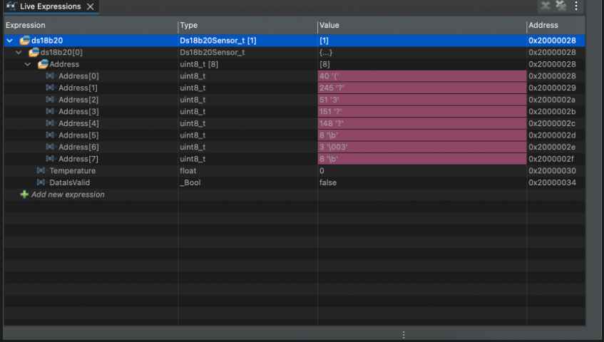
Success. Communication started. Although it doesn't read the temperature data accurately yet, it has started communicating.
Now, in the main function,
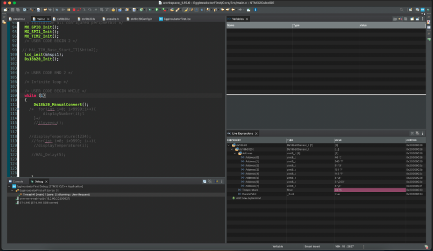
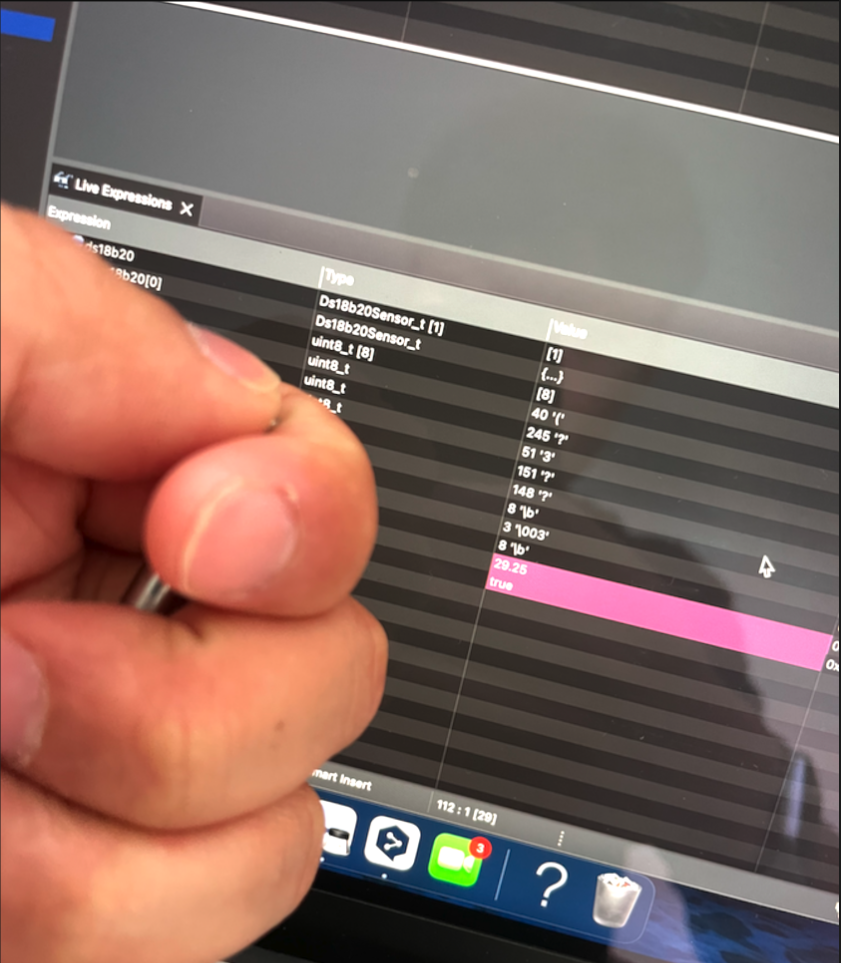
Using the Ds18b20_ManualConvert() function reads the temperature.
When you hold it to increase the heat, the temperature rises.
Since we previously had issues with the oneWire search, let's check if the oneWire search works correctly.

It works well.
Now, let's find out how the ID and comp ID bit can differ. To do this, let's observe the state of the GPIO when OneWire Low and High are triggered.
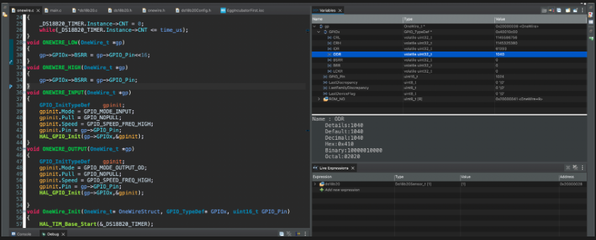
When it's High, it's 1040.
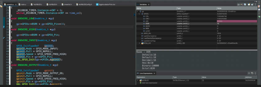
When it's Low, it's 16.
So, it's the same as before. It wasn't a GPIO issue before either.
So, it was a clock setting issue. How did we define 1 tick?
Was the counter period related to 1 tick?
I learned about prescaler, counter period, and counter mode in detail from this lecture: https://www.youtube.com/watch?v=94gsG0nUDs4
So,
Clock/prescaler = desired clock. 1/desired clock = time taken for 1 tick. Timer overflow = counter period x time taken for 1 tick
So,
8 / 8 = 1MHz
1/ 1MHz = 1 us
1 us x 0xFFFF = 65535 us
72 / 72 = 1MHz
1/ 1MHz = 1 us
1 us x 0xFFFF = 65535 us
The result is the same.
But why was the clock an issue?
The result should be the same.
In the end, the problem was solved. However, no matter how much I studied and thought about it, I couldn't find the reason why.
I suspect it might be due to overflow, noise issues, or the internal clock being less stable than the crystal.
Further study revealed that lower frequencies are more resistant to noise and thus more stable than higher frequencies.
In the end, I couldn't find the answer, but if anyone knows why, I would love to hear the explanation. Please let me know!!
Subscribe to my newsletter
Read articles from Sam Lee directly inside your inbox. Subscribe to the newsletter, and don't miss out.
Written by
