Understanding Class Diagrams: The Complete Guide
 Namra Ajmal
What is a Class Diagram?
UML (Unified Modeling Language) is a general-purpose modeling language that helps to model systems in various ways. One of the ways it provides this functionality is through class diagrams. A class diagram is a static structural diagram that represents the relationship of classes within a system.
Importance of Class diagrams
Design blueprint
Class diagrams in SE and OOAD are analogous to blueprints in architecture. As the blueprints allow us to plan and design the layout of building before starting construction, class diagrams also facilitate in planning and designing the software before the coding begins.
Problem-solving
Class diagrams provide a clear overview of the entire system which helps to identify potential threats and areas that require improvements or that can be handled more efficiently even before coding starts making the actual development process both time saving and monetarily efficient.
Documentation
Class diagrams act as documentation that can be referred to anytime during the entirety of software development life cycle (SDLC).
Basic components of a Class Diagram
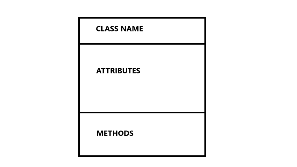
UML Class diagrams represent classes as boxes and each box is divided into three compartments.

The first compartment represents the name of the class. It should be centered and bold to emphasize its significance.
The second/middle compartment represents the attributes or properties of the class. It includes visibility and data type.
The third/last compartment includes the methods or functions that the class can perform along with their visibility. They also include return types and parameters (if required).
Visibility
In UML class diagrams visibility means whether a certain attribute or method can be seen or used by other classes or not. Following are the notations that are used to depict visibility.
Notation
+ (public): visible to all classes
- (private): visible only within the class
# (protected): visible to the subclasses
Multiplicity
Multiplicity in UML class diagrams defines the number of instances of one class that can be associated with a single instance of another class. It specifies the possible range of objects in a relationship, such as "one-to-one," "one-to-many," or "many-to-many."
Notation
0..1: Zero or one instance. This shows that an object may be optionally associated with one instance of the other class.
1: Exactly one instance. This indicates that each instance of a class is associated with exactly one instance of the other class.
1..*: One or more instances. This means that an instance must be associated with at least one instance of the other class.
0..*: Zero or more instances. This means there is no limit on the number of instances, and the association is optional.
Example: Composition between House and Room
A house must have at least one room but can contain multiple rooms, while a room belongs to exactly one house.
House [1] ◆---- [1..*] Room
Relationships in classes
Following are the relationships that can exist between classes.
Association
Association shows a connection between two classes where one class interacts with another. It indicates a "uses-a" or "works-with" relationship between classes.
Notation
Represented by a solid line between two classes. Multiplicity (like 1..* (1 to many), or 0..1) can be added to indicate the number of objects involved in the relationship.
Example
Inheritance (Generalization)
Inheritance, or generalization, represents a relationship where one class (subclass) inherits the properties and behaviors of another class (superclass). It allows code reusability by sharing attributes and methods from a parent class.
Notation
Represented by a solid line with a hollow triangle pointing from the subclass to the superclass.
Aggregation
Aggregation is a form of association that represents a "whole-part" relationship. The part can exist independently of the whole i.e. even if the whole is removed the part continues to exist.
Notation
Represented by a solid line with a hollow diamond near the "whole" class and the other end attached to the "part" class.
Composition
Composition is a stronger form of aggregation where the part ceases to exist without the whole. It represents a "contains-a" relationship.
Notation
Represented by a solid line with a filled diamond near the "whole" class and the other end attached to the "part" class.
Dependency
A dependency indicates that a class relies on another class to function, but the relationship is weaker and often temporary. It shows that changes in the supplier class might affect the dependent class.
Notation
Represented by a dashed line with an arrow pointing from the dependent class to the class it depends on.
Realization
Realization occurs when a class implements the methods and behaviors defined by an interface. It connects an interface to a class that provides concrete behavior for the abstract definitions.
Notation
Represented by a dashed line with a hollow triangle pointing from the implementing class to the interface.
Conclusion
Class diagrams play a vital role in both Software Engineering (SE) and Object-Oriented Analysis and Design (OOAD), providing a clear, visual representation of the structure and relationships within a system. By defining classes, attributes, methods, and the interactions between objects, class diagrams help in organizing and understanding complex systems. They enhance communication among developers and stakeholders, facilitate better design decisions, and serve as a blueprint for implementation. Mastering class diagrams is essential for anyone involved in system architecture and development, as they bridge the gap between high-level design and actual coding.
Subscribe to my newsletter
Read articles from Namra Ajmal directly inside your inbox. Subscribe to the newsletter, and don't miss out.
Written by
