Controlling Heater - AC Relay
 Sam Lee
One of the essential functions of an egg incubator is to control the heater. The egg incubator should turn the heater on when the temperature falls below a certain point and turn it off when the temperature rises above a certain point.
A significant amount of current is required to power the heater, but an MCU chip like the STM32 cannot supply enough current. How can we generate a large current using a small one? This is where transistors come into play.
By connecting a sufficient power source to the Collector and linking the Base to the MCU chip, the transistor can amplify the current when the MCU sends a signal.
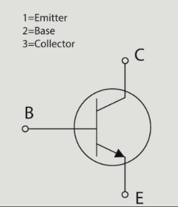
This is essentially how a relay module works. A relay is an electrical component that helps control high-power devices using a small DC current.
The module we will be using is the SRD-05VDC-SL-C.
https://www.build-electronic-circuits.com/how-a-relay-works/
From this website, I learned how to use an AC relay.
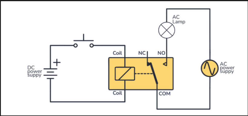
As shown in the diagram, there are DC and AC circuits, with the relay connecting the two. When the DC circuit is closed via a switch, current flows through the coil, switching the pin from NC to NO and closing the AC circuit.
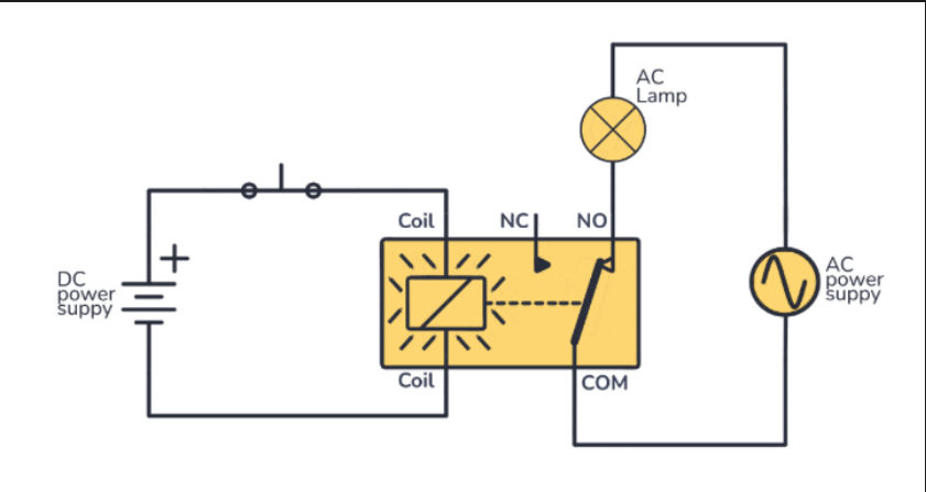
NO stands for Normally Open, NC stands for Normally Closed, and Com is Common, which is equivalent to Ground.
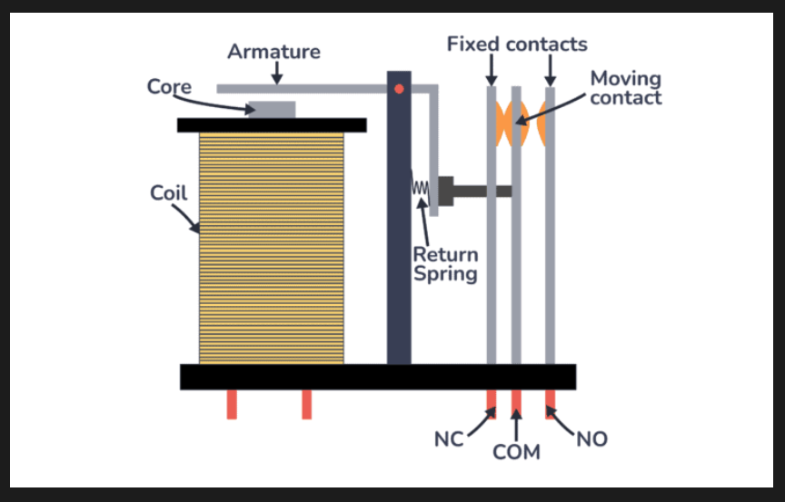
Inside the relay, it looks like this. To explain this, we need to cover some basic electrical knowledge.
Electricity has an interesting relationship with magnets. A changing electric field creates a magnetic field, and a changing magnetic field creates an electric field. This is known as electromagnetic induction. The core in the relay is a magnet, and the coil is a wire. When current flows through the coil, it changes the electric field, which in turn affects the magnetic field.
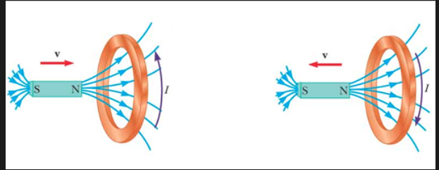
As you can see in the picture, there is a specific relationship between the direction of the current and the movement of the magnet. In other words, when current flows, it can exert a force that moves the magnet. In the relay, when current flows through the coil, it creates an electromagnetic field that attracts the armature. The armature then moves the connected COM contact from NC to NO.
So, when current is applied to the coil, it moves from NC to NO, closing the circuit connected to NO.
Now, let's connect everything.
Let's write code to turn on the GPIO when a switch is pressed and send the GPIO signal to the relay.
Since there will be many circuits to connect, we will start using a breadboard.
There are many explanations about breadboards available elsewhere, so I won't go into detail. Simply put, a breadboard is...
https://learn.sparkfun.com/tutorials/how-to-use-a-breadboard/all
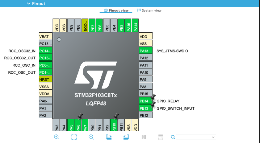
Set up two GPIO pins: one to receive the input from the switch and one to send the output to the relay.
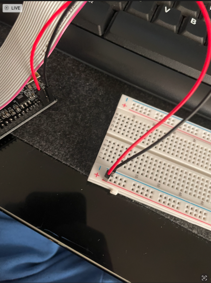
Provide power and ground.
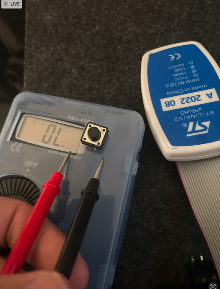
Using a multimeter, check the switch's connection direction. In the current photo, the left and right sides are disconnected, and pressing the switch connects them.
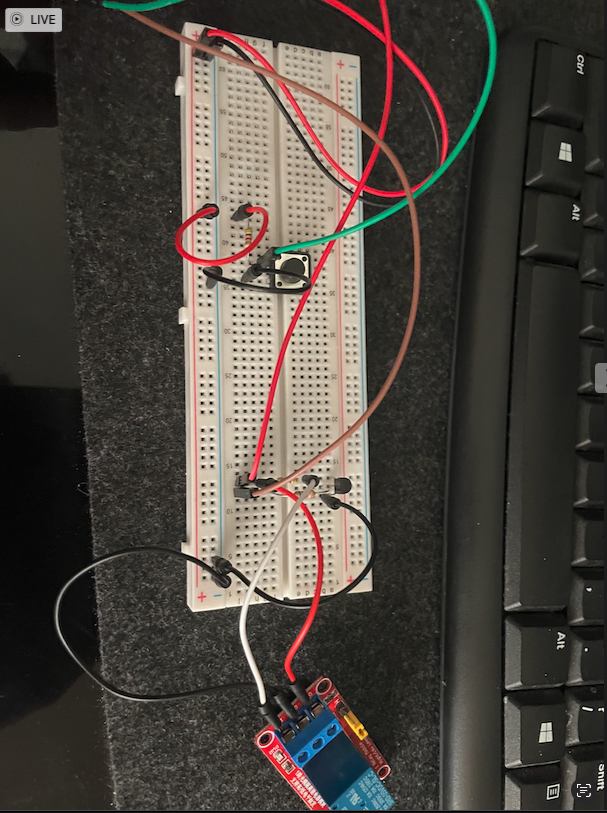
Connect the circuit as shown in the photo and now let’s start coding.
while (1)

{

// Ds18b20_Simple_Convert();

// temperature = my_ds18b20_Sensor.Temperature;


// HAL_Delay(5000);

//display_ssd1306(&startTime, "incubating", temperature, 1);


if(HAL_GPIO_ReadPin(GPIO_SWITCH_INPUT_GPIO_Port, GPIO_SWITCH_INPUT_Pin)){

HAL_GPIO_WritePin(GPIO_RELAY_GPIO_Port, GPIO_RELAY_Pin, 1);

}

else{

HAL_GPIO_WritePin(GPIO_RELAY_GPIO_Port, GPIO_RELAY_Pin, 0);

}

HAL_Delay(1000);

}


/* USER CODE END WHILE */


/* USER CODE BEGIN 3 */


/* USER CODE END 3 */

}
Comment out any unused modules to prevent them from operating.
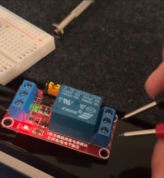
When the switch is pressed, the green light on the left side of the module turns on, indicating that the relay is active and that COM is connected to NO. This can be verified with a multimeter.
When the switch is turned off, it disconnects, and NC is connected to COM.
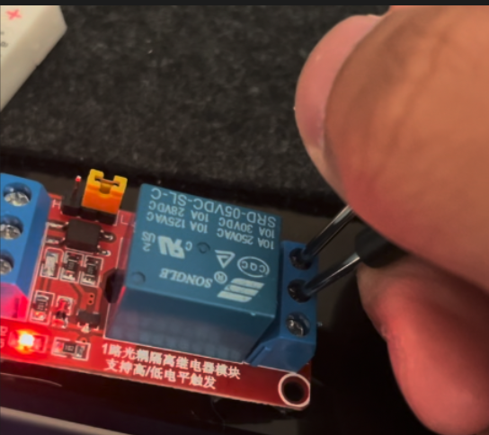
As mentioned earlier, you can hear a clicking sound as the armature moves in and out of the coil.
I tried to prepare a heater, but small heaters are hard to find, so I decided to use a hairdryer from home.
https://youtube.com/shorts/pKy_Z6dD42o?si=BJoiijFtKVuNhY32
(I think there is something wrong with the coil or armature in my Relay. I think the magnet is quite weak since I had to physically shake the relay module to move the armature inside. Thats why I tap the relay module after pressing the switch.)
I successfully implemented it, and here is how.
The STM32 controls the relay via GPIO. The relay controls the armature inside, moving the COM to control the NO and NC circuits.

One side of the heater plug is connected to the relay, and the other side is connected to an AC plug. When the relay connects the red wire of the heater plug, it forms a closed circuit, activating the heater.
This concludes the control of the AC relay. Finally, let's control the OLED.
P.S. It was really scary. I was afraid I might get electrocuted. I spent hours studying electricity and making sure I was creating the right circuit just to stay safe!
Subscribe to my newsletter
Read articles from Sam Lee directly inside your inbox. Subscribe to the newsletter, and don't miss out.
Written by
