Deployment of Transit Gateway
 Ravi Kumar Srivastava
Table of contents
1. Introduction
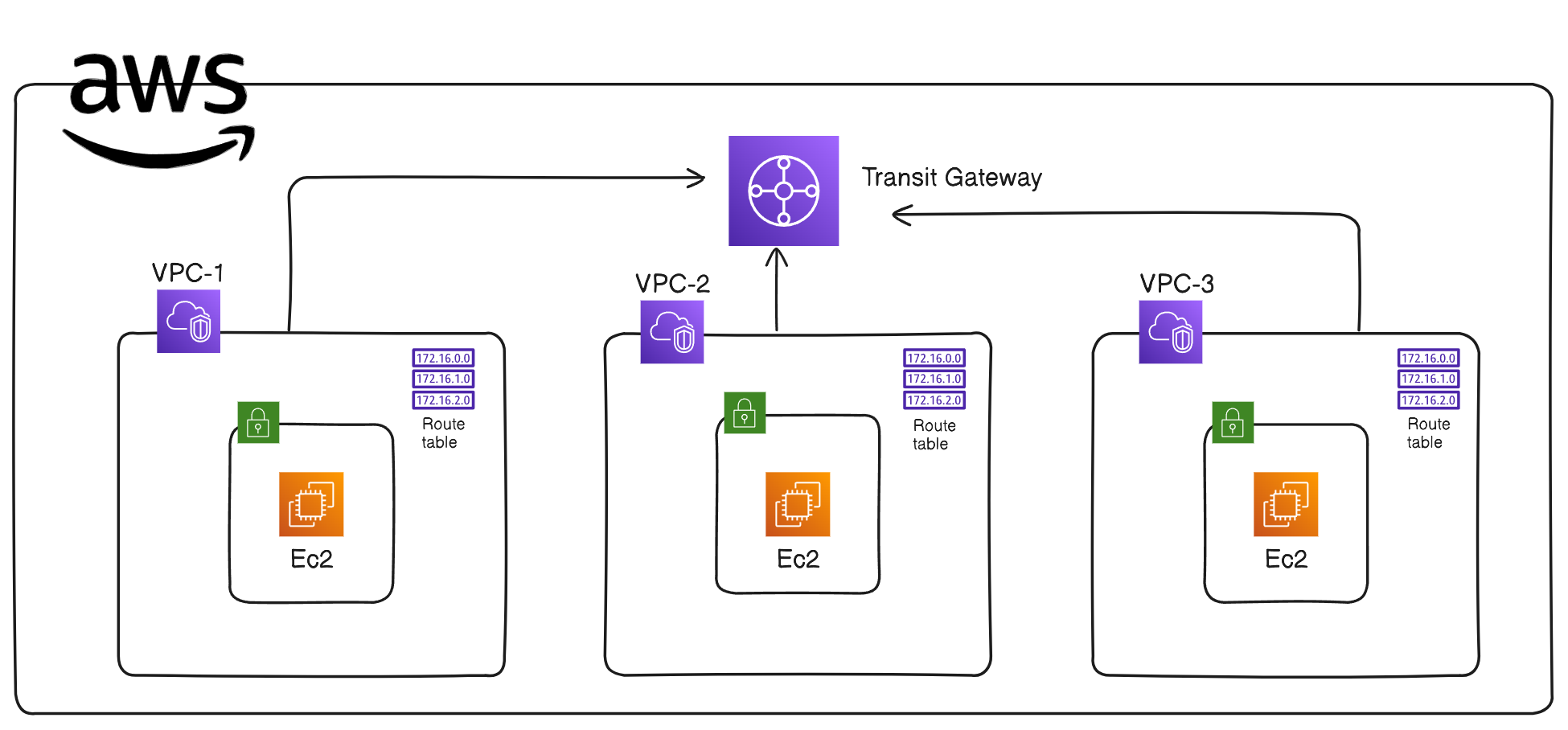
The goal of this project is to design and implement a secure, scalable, and redundant hub-and-spoke network architecture using AWS Transit Gateway. This architecture includes three VPCs (one hub and two spokes), three subnets, routing tables, internet gateways, NACLs, and three EC2 instances, each placed in a different subnet.
2. Network Architecture Overview
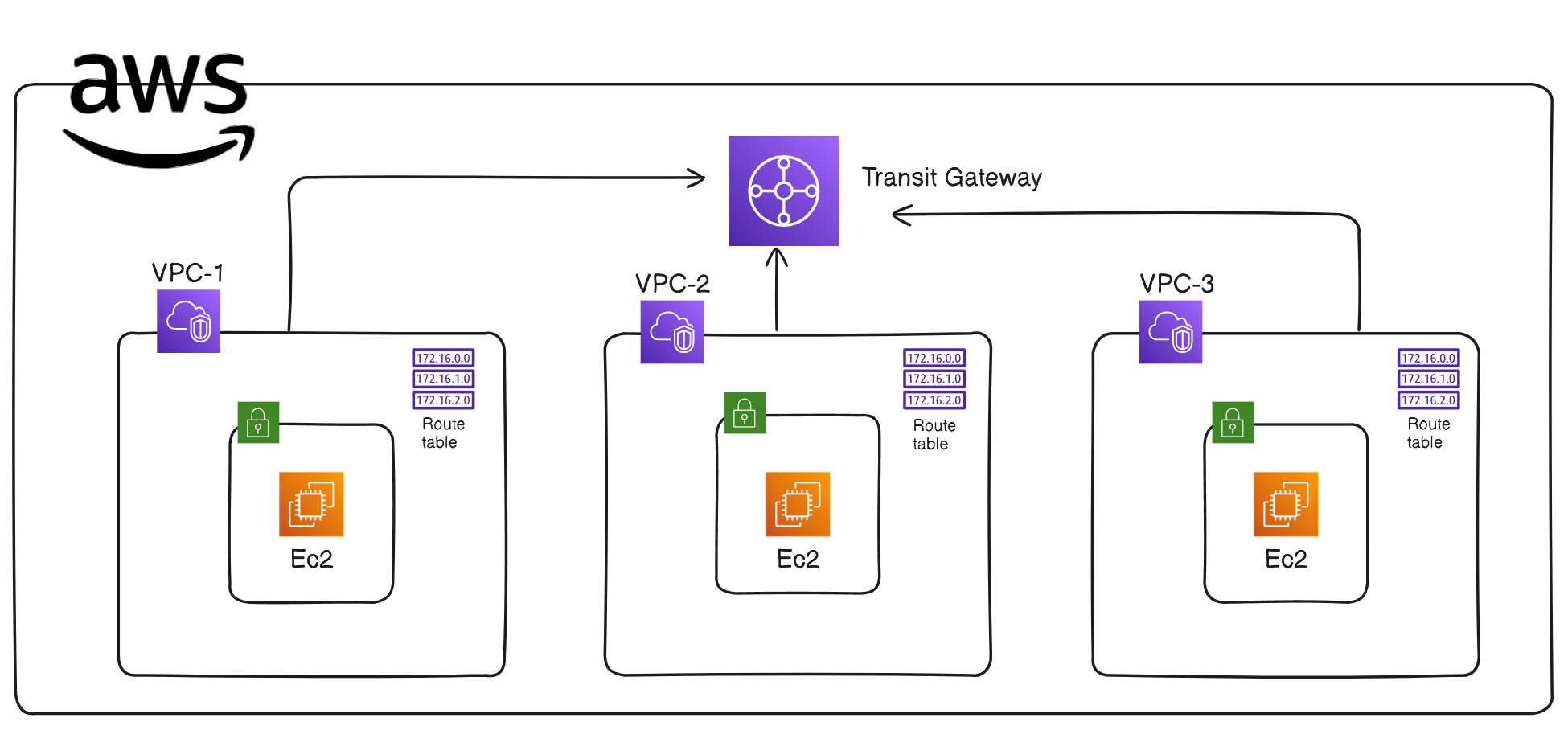
2.1 Architecture Diagram
2.2 Components of the Architecture
VPCs and Subnets:
VPC1 (Hub VPC):
CIDR Block: 10.0.0.0/16
Subnet: 10.0.1.0/24 (Public Subnet)
Internet Gateway: IGW attached to provide internet access.
VPC2 (Spoke VPC 1):
CIDR Block: 11.0.0.0/16
Subnet: 11.0.1.0/24 (Private Subnet)
Internet Gateway: IGW attached for internet access.
VPC3 (Spoke VPC 2):
CIDR Block: 12.0.0.0/16
Subnet: 12.0.1.0/24 (Private Subnet)
Internet Gateway: IGW attached for internet access.
2.3 Routing and Connectivity
Transit Gateway:
Deployed to act as a central hub to interconnect VPC1 (Hub) and the two spokes, VPC2 and VPC3.
Attachments:
VPC1 (10.0.0.0/16)
VPC2 (11.0.0.0/16)
VPC3 (12.0.0.0/16)
Route Tables:
VPC1 Route Table:
Route to VPC2 CIDR (11.0.0.0/16) via Transit Gateway.
Route to VPC3 CIDR (12.0.0.0/16) via Transit Gateway.
Default route (0.0.0.0/0) to its Internet Gateway (IGW).
VPC2 Route Table:
Route to VPC1 CIDR (10.0.0.0/16) via Transit Gateway.
Route to VPC3 CIDR (12.0.0.0/16) via Transit Gateway.
Default route (0.0.0.0/0) to its Internet Gateway (IGW).
VPC3 Route Table:
Route to VPC1 CIDR (10.0.0.0/16) via Transit Gateway.
Route to VPC2 CIDR (11.0.0.0/16) via Transit Gateway.
Default route (0.0.0.0/0) to its Internet Gateway (IGW).
3. Security Considerations
3.1 Network Security Groups (SGs)
VPC1 SG:
Allow SSH (port 22) and ICMP (ping) from VPC2 (11.0.1.0/24) and VPC3 (12.0.1.0/24).
Allow outbound traffic to VPC2 and VPC3.
VPC2 SG:
Allow SSH (port 22) and ICMP (ping) from VPC1 (10.0.1.0/24).
Allow outbound traffic to VPC1.
VPC3 SG:
Allow SSH (port 22) and ICMP (ping) from VPC1 (10.0.1.0/24).
Allow outbound traffic to VPC1.
3.2 Network Access Control Lists (NACLs)
VPC1 NACL:
Inbound Rules:
Allow traffic from VPC2 and VPC3 CIDRs.
Allow traffic from 0.0.0.0/0 for necessary ports like HTTPS (443).
Outbound Rules:
Allow traffic to VPC2 and VPC3 CIDRs.
Allow outbound traffic to 0.0.0.0/0 for all ports.
VPC2 NACL:
Inbound Rules:
- Allow traffic from VPC1 CIDR (10.0.1.0/24).
Outbound Rules:
- Allow traffic to VPC1 CIDR.
VPC3 NACL:
Inbound Rules:
- Allow traffic from VPC1 CIDR (10.0.1.0/24).
Outbound Rules:
- Allow traffic to VPC1 CIDR.
3.3 Additional Security Measures
Transit Gateway Routing:
- Controls inter-VPC traffic and ensures that communication between spokes is routed through VPC1 (Hub).
Use of Internet Gateways:
- Each VPC has its own Internet Gateway to handle internet-bound traffic, allowing for separate control over inbound and outbound internet traffic for each VPC.
4. Scalability and Redundancy
Scalability:
AWS Transit Gateway enables easy addition of more VPCs without creating new peering connections.
Future scalability is supported by allowing more VPC attachments to the Transit Gateway.
Redundancy:
Multi-AZ deployment of resources, including Transit Gateway, ensures high availability and fault tolerance.
Redundant network paths through the Transit Gateway prevent a single point of failure.
5. Implementation Steps
Step 1: Create VPCs and Subnets
VPC1 (Hub VPC):
Create 10.0.0.0/16 VPC with a 10.0.1.0/24 public subnet.
Attach an Internet Gateway and configure a route to 0.0.0.0/0.
VPC2 (Spoke VPC 1):
Create 11.0.0.0/16 VPC with a 11.0.1.0/24 private subnet.
Attach an Internet Gateway and configure a route to 0.0.0.0/0.
VPC3 (Spoke VPC 2):
Create 12.0.0.0/16 VPC with a 12.0.1.0/24 private subnet.
Attach an Internet Gateway and configure a route to 0.0.0.0/0.
Step 2: Configure Transit Gateway
Create Transit Gateway:
- Attach VPC1, VPC2, and VPC3.
Update Route Tables:
- Configure routes in VPC1, VPC2, and VPC3 to direct traffic through the Transit Gateway.
Step 3: Configure Security Groups and NACLs
Create and apply Security Groups to control traffic between VPCs.
Create and configure NACLs for each subnet to allow/deny traffic as per the security policy.
Step 4: Deploy EC2 Instances
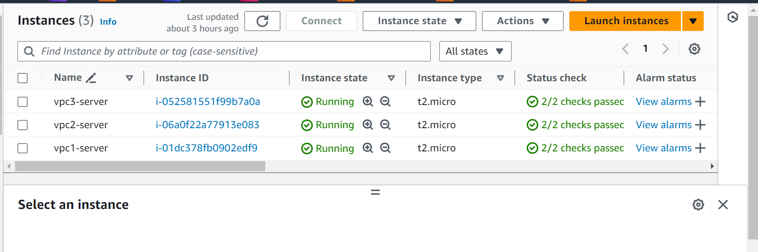
Launch EC2 instances in each subnet for testing connectivity:
VPC1 EC2 Instance:
- Public IP enabled, SSH access configured.
VPC2 and VPC3 EC2 Instances:
- Public IP enabled, SSH access configured.
6. Testing and Verification
Connectivity Testing:
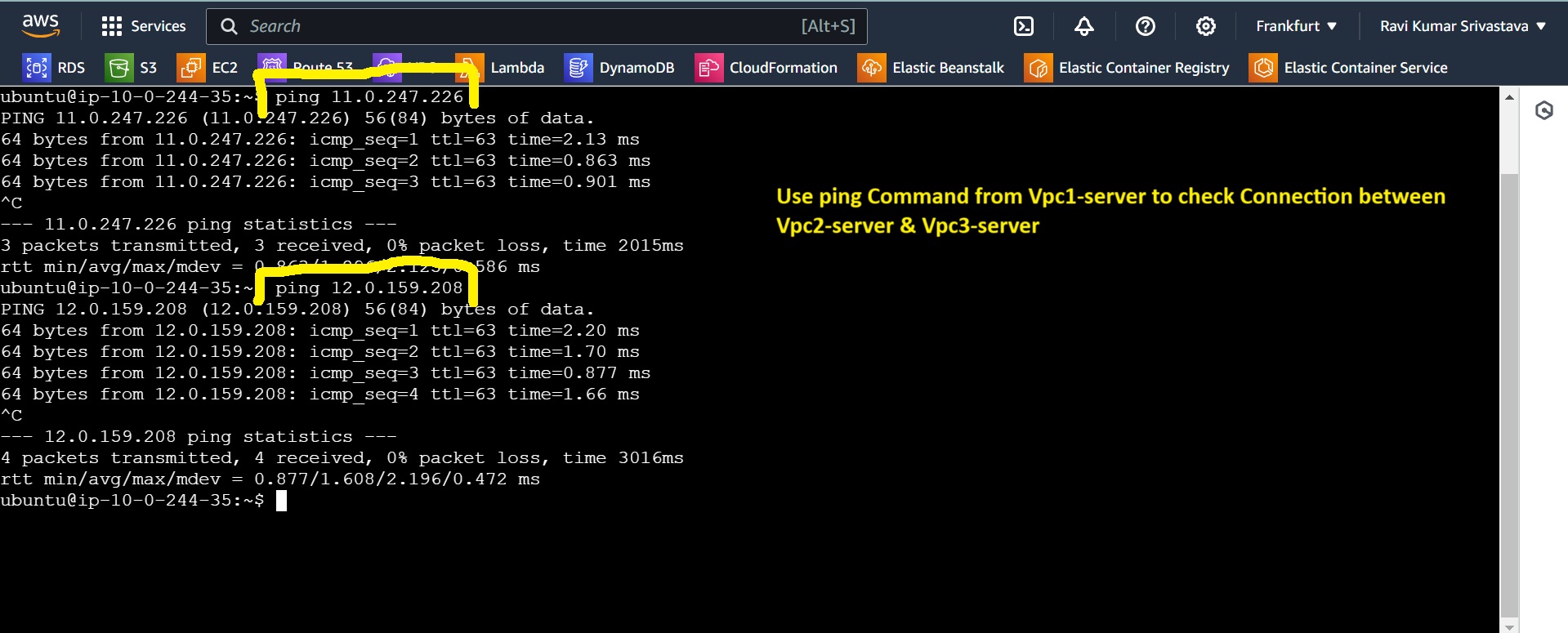
Verify that EC2 instances in VPC2 and VPC3 can communicate only through VPC1 using the Transit Gateway.
Confirm that SSH and ICMP connections are allowed as per the configured Security Groups.
Security Testing:
- Test NACLs and Security Groups to ensure unauthorized traffic is blocked.
7. Issues and Resolutions
Issue 1: Instances in VPCs were not communicating correctly.
- Resolution: Corrected Transit Gateway route configuration and ensured proper NACL rules.
Issue 2: Overly permissive inbound rules allowed unnecessary internet access.
- Resolution: Restricted Security Group rules to only necessary IP ranges.
8. Conclusion
The designed architecture effectively uses AWS Transit Gateway to establish a scalable, redundant, and secure hub-and-spoke network. It allows controlled communication between VPCs, ensuring the desired traffic flow and enhanced security.
Here Are Some Important Screenshots of Configuration Related to This Hub and Spoke
List of VPCs Used in this Project:

List of Subnets:

Route Tables :

Internet Gateways:

Network ACLs

Transit Gateways :

Transit Gateways Attachments:

EC2 Instances :
Checking Connection from Server1 to Server 2 and Server 3
Checking connection from server 2 to Server 1 and Server 3
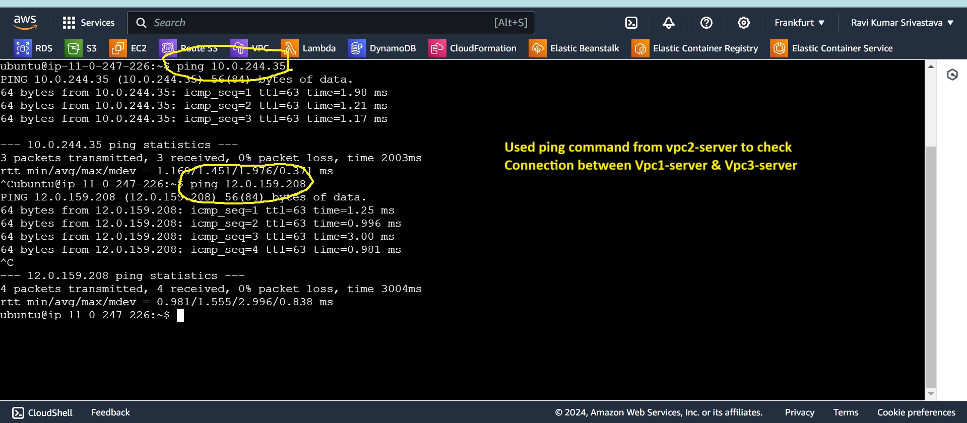
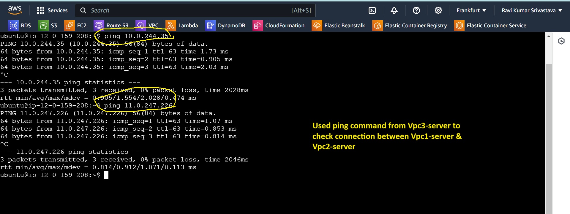
Checking connection from server 3 to Server 1 and Server 2
Subscribe to my newsletter
Read articles from Ravi Kumar Srivastava directly inside your inbox. Subscribe to the newsletter, and don't miss out.
Written by
