Controlling OLED
 Sam Lee
Hatching an egg takes about 21 days. We will use an OLED to check how long the egg incubator has been running. Displaying it in a clear manner would be ideal.
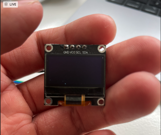
The OLED module we will use is the jmd0.96d-1 module.
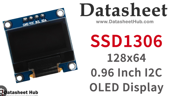
It looks like this and is also known as SSD1306.
Let's look for the datasheet and example code.
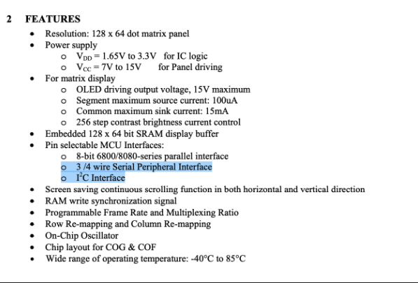
According to the datasheet, it has a resolution of 128 x 64 bits and can be used with either I2C or SPI.
Since we have previously worked with SPI on an LCD display, let's try using I2C this time.
Library code: https://github.com/afiskon/stm32-ssd1306/tree/master
This short video provides a simple tutorial on the module: https://www.youtube.com/watch?v=97_Vyph9EzM
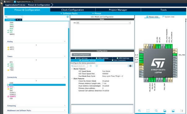
Copy all the files into the folder.
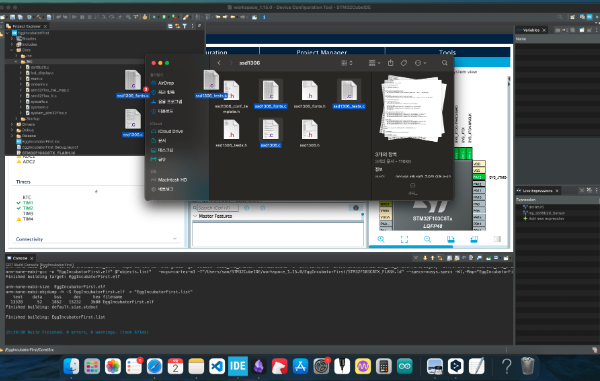
Then, build all and fix any errors that appear.
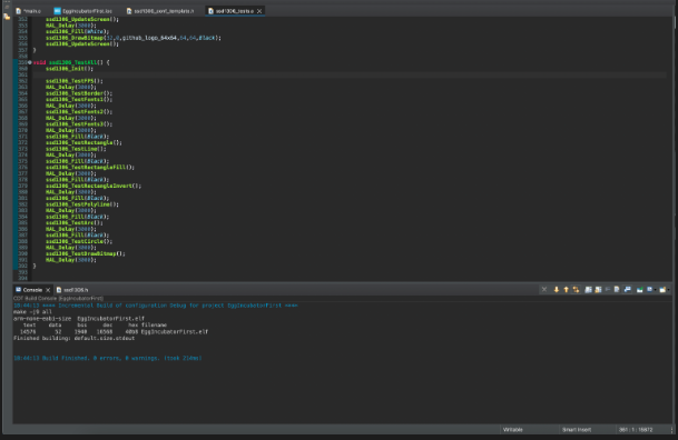
After fixing all errors, go to ssd1306_test.c. There is a function called test_all, which includes Init and runs all the functions of ssd1306. Run the test_all function to see if it works.
Before running, connect the pins.
As before, use black for ground, red for power, and choose different colors for the remaining two pins.
As you can see from the number of pins, there are two left after power and ground.
Communication is done using the SCL and SDA pins.
I2C communicates with only clock and data lines, without needing an address line. Therefore, multiple masters can control one device. In contrast, SPI requires an address line, also known as the Chip Select Pin. Because I2C sends the address with the data to indicate which device it is communicating with, it is slower than SPI.
In summary, the advantage of I2C is that multiple masters can control one device, but its disadvantages include lower speed and potential bus collisions if multiple masters access the bus simultaneously.
Let's briefly understand how I2C communication works.
Start Condition: The master device generates a start condition by switching the SDA line from high to low while the SCL line is high.
Slave Address Transmission: The master device sends the 7-bit address of the slave device, with the last bit indicating read/write mode.
ACK/NACK: The slave device sends an ACK (Acknowledge) signal if it recognizes its address, otherwise, it sends a NACK (Not Acknowledge) signal.
Data Transmission: The master and slave devices exchange data one byte at a time. After each byte, they exchange ACK/NACK signals to confirm data transmission.
Stop Condition: The master device generates a stop condition by switching the SDA line from low to high while the SCL line is high, ending the communication.
These five steps constitute I2C communication. Due to the address bit transmission and acknowledgment signals, I2C is not used for high-speed communication. For high-speed communication, SPI is generally used.
To test the SSD1306 module, comment out the ds18b20 or LCD code we previously created and run the test.
/* USER CODE BEGIN 2 */


ssd1306_TestAll();

// lcd_init(&hspi1);

// Ds18b20_Init_one_device();

// HAL_TIM_Base_Start_IT(&htim1);
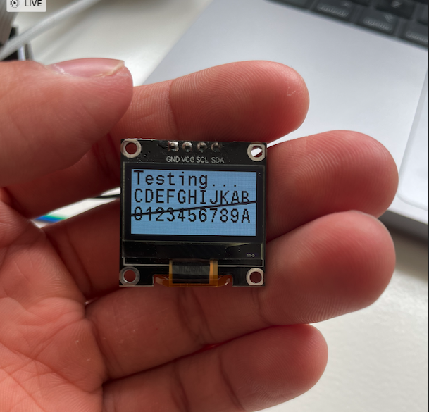
It works very well.
We can draw pictures, write text, and the screen updates quickly.
It's surprising how easily it works, considering the effort, time, and frustration we experienced with the LCD and ds18b20 sensor.
Let's stop the unnecessary talk and see how the ssd1306 sensor works.
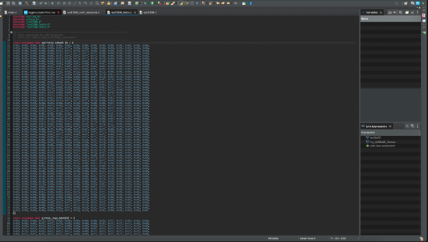
As you can see, it draws logos or pictures using a 128x64 bit array. It seems to use this data to display on the OLED.
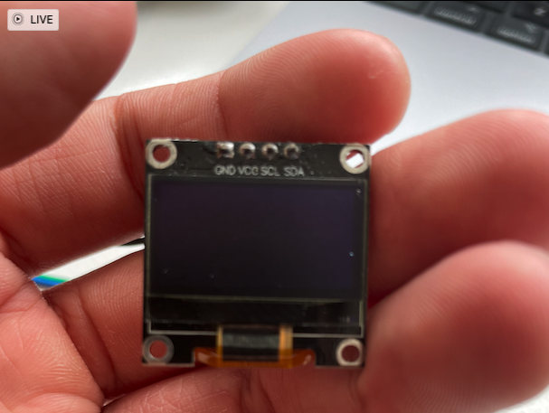
The first function is ssd1306_TestBorder, which shows a dot moving from (0, 0) to (128, 0), then to (128, 64), then to (0, 64), and back to (0, 0). It shows a dot moving around the border.
void ssd1306_TestBorder() {

ssd1306_Fill(Black);

uint8_t x = 0;

uint8_t y = 0;

do {

ssd1306_DrawPixel(x, y, Black);


if((y == 0) && (x < (SSD1306_WIDTH-1)))

x++;

else if((x == (SSD1306_WIDTH-1)) && (y < (SSD1306_HEIGHT-1)))

y++;

else if((y == (SSD1306_HEIGHT-1)) && (x > 0))

x--;

else

y--;


ssd1306_DrawPixel(x, y, White);

ssd1306_UpdateScreen();

HAL_Delay(5);

} while(x > 0 || y > 0);

HAL_Delay(1000);

}
First, it fills the screen with black using ssd1306_Fill(Black); then draws a pixel with ssd1306_DrawPixel(x, y, White); and updates the screen with ssd1306_UpdateScreen();.
This suggests that there is a buffer where something is drawn, and updating the screen uploads the buffer to the OLED.
Let's look at one more function before moving to the SSD1306.c file.
void ssd1306_TestFonts1() {

uint8_t y = 0;

ssd1306_Fill(Black);


#ifdef SSD1306_INCLUDE_FONT_16x26

ssd1306_SetCursor(2, y);

ssd1306_WriteString("Font 16x26", Font_16x26, White);

y += 26;

#endif


#ifdef SSD1306_INCLUDE_FONT_11x18

ssd1306_SetCursor(2, y);

ssd1306_WriteString("Font 11x18", Font_11x18, White);

y += 18;

#endif


#ifdef SSD1306_INCLUDE_FONT_7x10

ssd1306_SetCursor(2, y);

ssd1306_WriteString("Font 7x10", Font_7x10, White);

y += 10;

#endif


#ifdef SSD1306_INCLUDE_FONT_6x8

ssd1306_SetCursor(2, y);

ssd1306_WriteString("Font 6x8", Font_6x8, White);

#endif


ssd1306_UpdateScreen();

}
Using the ssd1306_SetCursor(2, y); function, we set where to write, then use ssd1306_WriteString("Font 6x8", Font_6x8, White); to write something to the buffer, and again update the screen with ssd1306_UpdateScreen();.
So, we use functions like ssd1306_WriteString() and ssd1306_DrawPixel(); to write to the buffer, then update the screen with ssd1306_UpdateScreen().
Let's look at these functions in detail.
/*

* Draw one pixel in the screenbuffer

* X => X Coordinate

* Y => Y Coordinate

* color => Pixel color

*/

void ssd1306_DrawPixel(uint8_t x, uint8_t y, SSD1306_COLOR color) {

if(x >= SSD1306_WIDTH || y >= SSD1306_HEIGHT) {

// Don't write outside the buffer

return;

}

// Draw in the right color

if(color == White) {

SSD1306_Buffer[x + (y / 8) * SSD1306_WIDTH] |= 1 << (y % 8);

} else {

SSD1306_Buffer[x + (y / 8) * SSD1306_WIDTH] &= ~(1 << (y % 8));

}

}
The ssd1306_DrawPixel function takes x and y coordinates to decide which bit's color to change.
It checks if x and y are within the 128x64 range and updates the buffer array.
if(color == White) {

SSD1306_Buffer[x + (y / 8) * SSD1306_WIDTH] |= 1 << (y % 8);


/* Draw a bitmap */

void ssd1306_DrawBitmap(uint8_t x, uint8_t y, const unsigned char* bitmap, uint8_t w, uint8_t h, SSD1306_COLOR color) {

int16_t byteWidth = (w + 7) / 8; // Bitmap scanline pad = whole byte

uint8_t byte = 0;


if (x >= SSD1306_WIDTH || y >= SSD1306_HEIGHT) {

return;

}


for (uint8_t j = 0; j < h; j++, y++) {

for (uint8_t i = 0; i < w; i++) {

if (i & 7) {

byte <<= 1;

} else {

byte = (*(const unsigned char *)(&bitmap[j * byteWidth + i / 8]));

}


if (byte & 0x80) {

ssd1306_DrawPixel(x + i, y, color);

}

}

}

return;

}
The ssd1306_DrawBitmap() function uses a loop to turn on each bit one by one using the ssd1306_DrawPixel() function.
After writing the desired data to the buffer, we need to update it.
/* Write the screenbuffer with changed to the screen */

void ssd1306_UpdateScreen(void) {

// Write data to each page of RAM. Number of pages

// depends on the screen height:

//

// * 32px == 4 pages

// * 64px == 8 pages

// * 128px == 16 pages

for(uint8_t i = 0; i < SSD1306_HEIGHT/8; i++) {

ssd1306_WriteCommand(0xB0 + i); // Set the current RAM page address.

ssd1306_WriteCommand(0x00 + SSD1306_X_OFFSET_LOWER);

ssd1306_WriteCommand(0x10 + SSD1306_X_OFFSET_UPPER);

ssd1306_WriteData(&SSD1306_Buffer[SSD1306_WIDTH*i],SSD1306_WIDTH);

}

}
Four commands are used.
The comments indicate that the SSD1306 OLED manages the screen by dividing it into multiple pages. Each page is 8 pixels high, so a 64-pixel high screen has 8 pages. This function updates all pages sequentially.
ssd1306_WriteCommand(0xB0 + i): Sets the address of the current page to update. i represents the page number, starting from 0.
ssd1306_WriteCommand(0x00 + SSD1306_X_OFFSET_LOWER) and ssd1306_WriteCommand(0x10 + SSD1306_X_OFFSET_UPPER): Sets the starting position (X coordinate) on the screen to output data. SSD1306_X_OFFSET_LOWER and SSD1306_X_OFFSET_UPPER represent the lower and upper bytes, respectively.
ssd1306_WriteData(&SSD1306_Buffer[SSD1306_WIDTH * i], SSD1306_WIDTH): Sends the data stored in the buffer for the corresponding page to the OLED. SSD1306_Buffer points to the buffer storing the screen data, and SSD1306_WIDTH represents the number of pixels in a line.
The for loop iterates through all the pages of the screen.
SSD1306_HEIGHT(64)/8 represents the total number of pages.
SSD1306_Buffer[SSD1306_WIDTH * i] calculates the starting address of the current page.
The ssd1306_WriteData function sends the buffer data to the OLED.
Now that we know how to display, let's display what we want.
Since the OLED can display images, it would be nice to show a logo at the beginning. As the temperature sensor and LCD module take time to initialize, we can show a hatching chick image while other modules are booting, then display the information we want to show simultaneously with the LCD module.
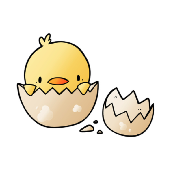
This picture is very cute, so let's convert it to pixels.
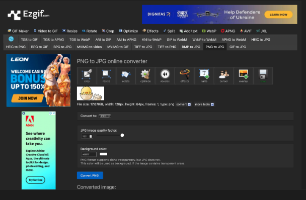
Resize the image on a website, then convert the resized image to a bitmap on an image to cpp website.
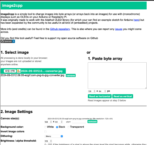
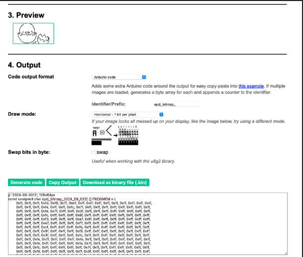
Convert it to a bitmap.
After converting, paste it into ssd1306_test.c and test it.
void ssd1306_TestDrawBitmap()

{

ssd1306_Fill(White);

ssd1306_DrawBitmap(0,0,garfield_128x64,128,64,Black);

ssd1306_UpdateScreen();

HAL_Delay(3000);

ssd1306_Fill(Black);

ssd1306_DrawBitmap(32,0,github_logo_64x64,64,64,White);

ssd1306_UpdateScreen();

HAL_Delay(3000);

ssd1306_Fill(White);

ssd1306_DrawBitmap(32,0,github_logo_64x64,64,64,Black);

//testing egg hatching bitmap

ssd1306_UpdateScreen();

HAL_Delay(3000);

ssd1306_Fill(Black);

ssd1306_DrawBitmap(0,0,egg_hatching_128x64,128,64,Black);

ssd1306_UpdateScreen();

}
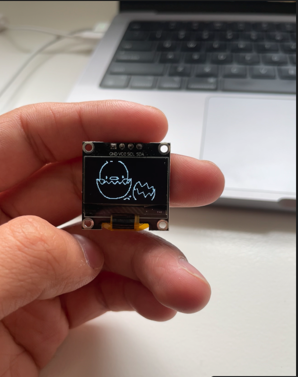
It works perfectly.
What should we display during booting?
Let's ask AI.
Hatching Egg Animation: A simple animation of an egg cracking and a chick emerging can intuitively show the main function of the incubator.
Loading Bar: Display a loading bar during booting to inform the user of the wait and visually show the progress.
Blinking Icons: Small dots or icons blinking sequentially can represent the booting process.
Smooth transition to the main screen after booting:
Fade In/Out: Use a fade-in or fade-out effect to smoothly transition, enhancing visual satisfaction.
Slide: Use a sliding effect to transition the screen smoothly.
Example:
Logo: Display a large egg-shaped logo representing the incubator in the center of the screen.
Animation: Show an animation of an egg cracking and a chick emerging with the text "Hatching...".
Slogan: Display a small slogan like "Your little ones' best start" below the logo.
The key is to give the user a positive first impression and concisely show the product's features.
So, let's show the egg in the center, wait for a moment, then make the egg shake two or three times, and show the chick hatching.
When the egg is in the center, there will be no text. When the egg starts shaking, display "Hatching..." below.
When the chick hatches, display the slogan "Your little ones' best start" below.
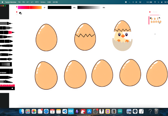
These images are created. The egg will be still, then tilt left twice, return to the center, tilt right, and return to the center three times.
When the egg is still, there is no text. When it starts shaking, display "Hatching...". When the chick hatches, display the slogan.

Resize the images.
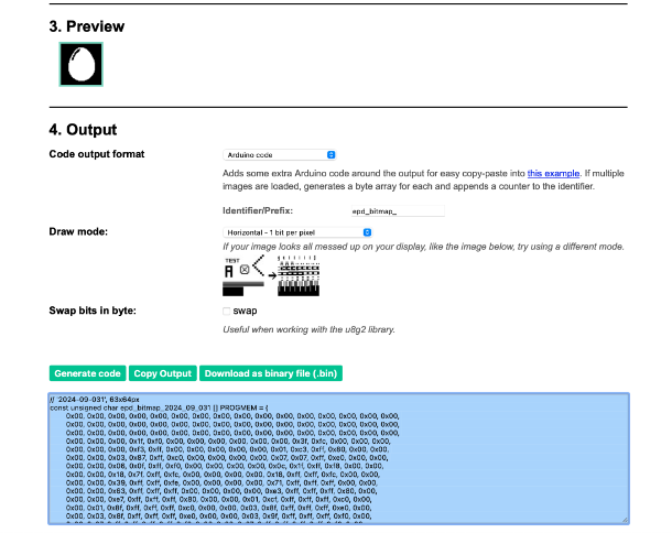
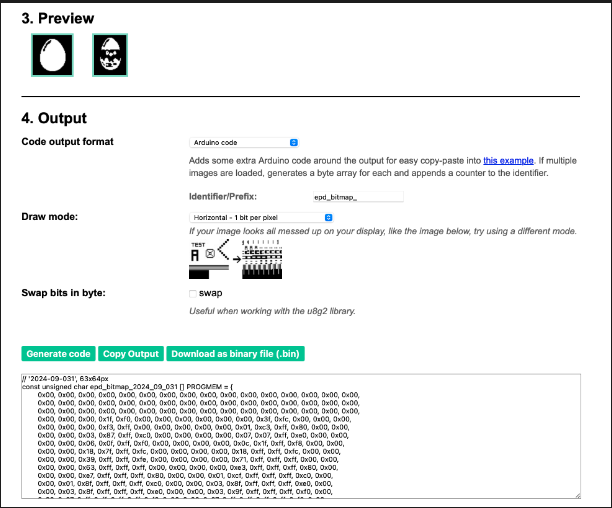
I tried to show a chick breaking out of the egg, but it was too difficult to draw with such low resolution, so I decided to use the first picture.
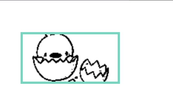
So, we have the egg, egg_tilted_left_1, egg_tilted_left_2, egg_tilted_right_1, egg_tilted_right_2, and egg_hatched images.
Start with the egg, wait for 2 seconds, then:
egg -> egg_tilted_left_1 -> egg_tilted_left_2 -> egg_tilted_left_1 -> egg -> egg_tilted_right_1 -> egg_tilted_right_2 -> egg_tilted_right_1 -> egg
This completes one shake cycle.
In pictures, it looks like this: 1, 2, 3, 4 completes one cycle.
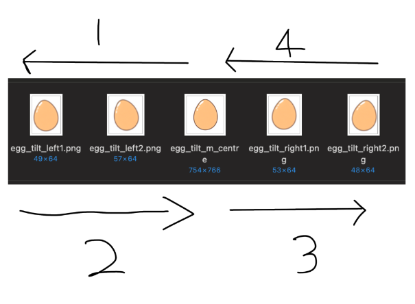
Resize and convert these 5 images to bitmaps.

Convert all 5 images to bitmaps.
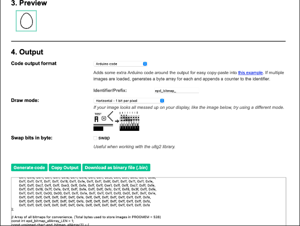
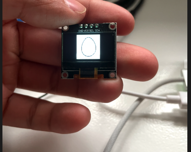
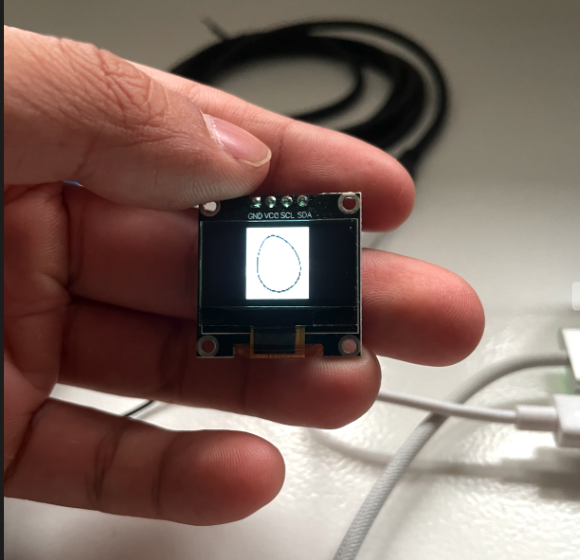
I didn't take pictures of all, but this is how the egg shaking is expressed. I will show it in the final demonstration video.
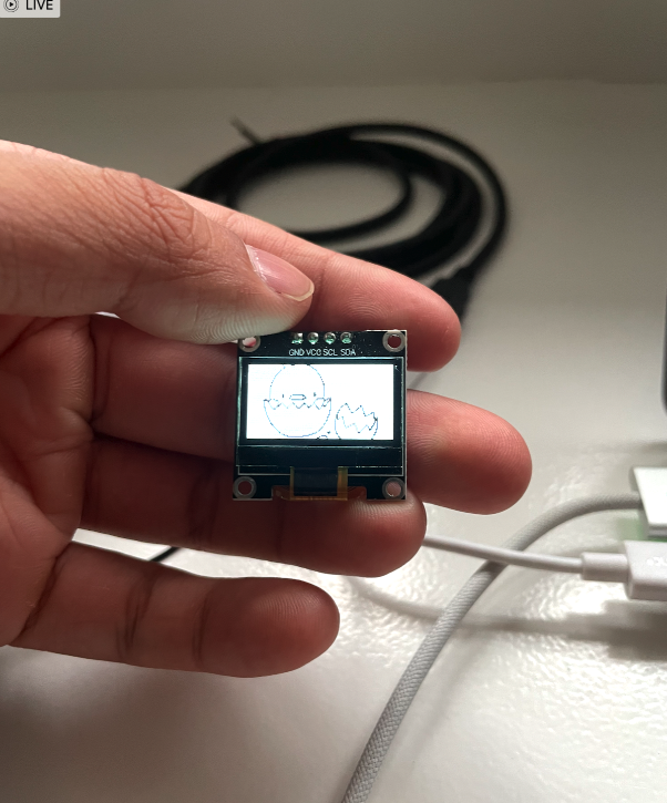
Next, the egg hatching.
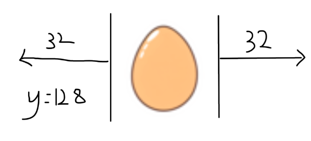
After the egg shakes, we will show the egg cracking.
Draw the crack on the egg without using ssd1306_Fill(Black); and use draw pixel to draw the crack.
The detailed code for this is in ssd1306_draw_egg_breaking().
When the egg starts cracking, display "Hatching...". When the chick hatches, display the slogan "Your little ones' best start" below.
The egg shakes twice, cracks, and the chick hatches during booting.
Include the boot animation in the ssd1306_egg_incubator_booting() function along with the init.
Since this runs only once, include it in the init part before the while() loop in main.c.
After booting, we need to display the incubator machine status in real-time.
In the next blog post, we will create an interface to continuously display the incubator status during operation.
Final Code
void ssd1306_draw_egg_shaking(){

//egg standing still

ssd1306_Fill(Black);

ssd1306_DrawBitmap(32,0,egg_centre_63x64,63,64,White);

ssd1306_UpdateScreen();

HAL_Delay(1000);


//Egg shaking starts

ssd1306_Fill(Black);

ssd1306_DrawBitmap(39,0,egg_tilt_left1_49x64,49,64,White);

ssd1306_UpdateScreen();

HAL_Delay(200);


ssd1306_Fill(Black);

ssd1306_DrawBitmap(35,0,egg_tilt_left2_57x64,57,64,White);

ssd1306_UpdateScreen();

HAL_Delay(200);


ssd1306_Fill(Black);

ssd1306_DrawBitmap(32,0,egg_centre_63x64,63,64,White);

ssd1306_UpdateScreen();

HAL_Delay(200);


ssd1306_Fill(Black);

ssd1306_DrawBitmap(37,0,egg_tilt_right1_53x64,53,64,White);

ssd1306_UpdateScreen();

HAL_Delay(200);


ssd1306_Fill(Black);

ssd1306_DrawBitmap(40,0,egg_tilt_right2_48x64,48,64,White);

ssd1306_UpdateScreen();

HAL_Delay(200);


ssd1306_Fill(Black);

ssd1306_DrawBitmap(37,0,egg_tilt_right1_53x64,53,64,White);

ssd1306_UpdateScreen();

HAL_Delay(200);


//egg standing still

ssd1306_Fill(Black);

ssd1306_DrawBitmap(32,0,egg_centre_63x64 ,63,64,White);

ssd1306_UpdateScreen();

HAL_Delay(1000);


}


void ssd1306_draw_egg_breaking(){

//egg breaking

int x = 44;

int y = 30;

int crack_height = 0;

int direction = 1;

int buffer = 0;


ssd1306_SetCursor(35, 55);

ssd1306_WriteString("Hatching..", Font_6x8, Black);

ssd1306_UpdateScreen();


//draw from 44 < x < 84


//draw from 30 < y < 33

// to make y fluctuate from 30~33, use an equation y = y + buffer+ crack_height*direction

// Y must be going from 30 to 33, and come back to 30 again and repeat. (30 - 31 - 32 - 33 - 32 - 31 - 30 * n times)


while(x<84){

ssd1306_DrawPixel(x, y + buffer+ crack_height*direction, Black);

ssd1306_UpdateScreen();

HAL_Delay(50);


x++;

crack_height++;

if(crack_height ==4){

crack_height =0;


if(direction ==1){

direction =-1;

buffer =3;

}

else{

direction =1;

buffer =0;

}


}


}


}


void ssd1306_draw_egg_hatching(){

HAL_Delay(3000);

ssd1306_Fill(Black);

ssd1306_DrawBitmap(0,0,egg_hatching_128x64,128,64,White);


ssd1306_SetCursor(0, 45);

ssd1306_WriteString("Your little ones' ", Font_6x8, Black);

ssd1306_SetCursor(45, 55);

ssd1306_WriteString("best start", Font_6x8, Black);


ssd1306_UpdateScreen();


ssd1306_UpdateScreen();


}


void ssd1306_egg_incubator_booting(){

ssd1306_Init();

ssd1306_draw_egg_shaking();

ssd1306_draw_egg_shaking();

ssd1306_draw_egg_breaking();

ssd1306_draw_egg_hatching();

}
In this post, we explored porting the OLED module library and learned about I2C communication. We used the OLED module to implement the egg incubator intro. In the next post, we will implement a status window that will always be displayed while the machine is operating.
Subscribe to my newsletter
Read articles from Sam Lee directly inside your inbox. Subscribe to the newsletter, and don't miss out.
Written by
