3D Meshing in Abaqus CAE
 Vishal Sharma
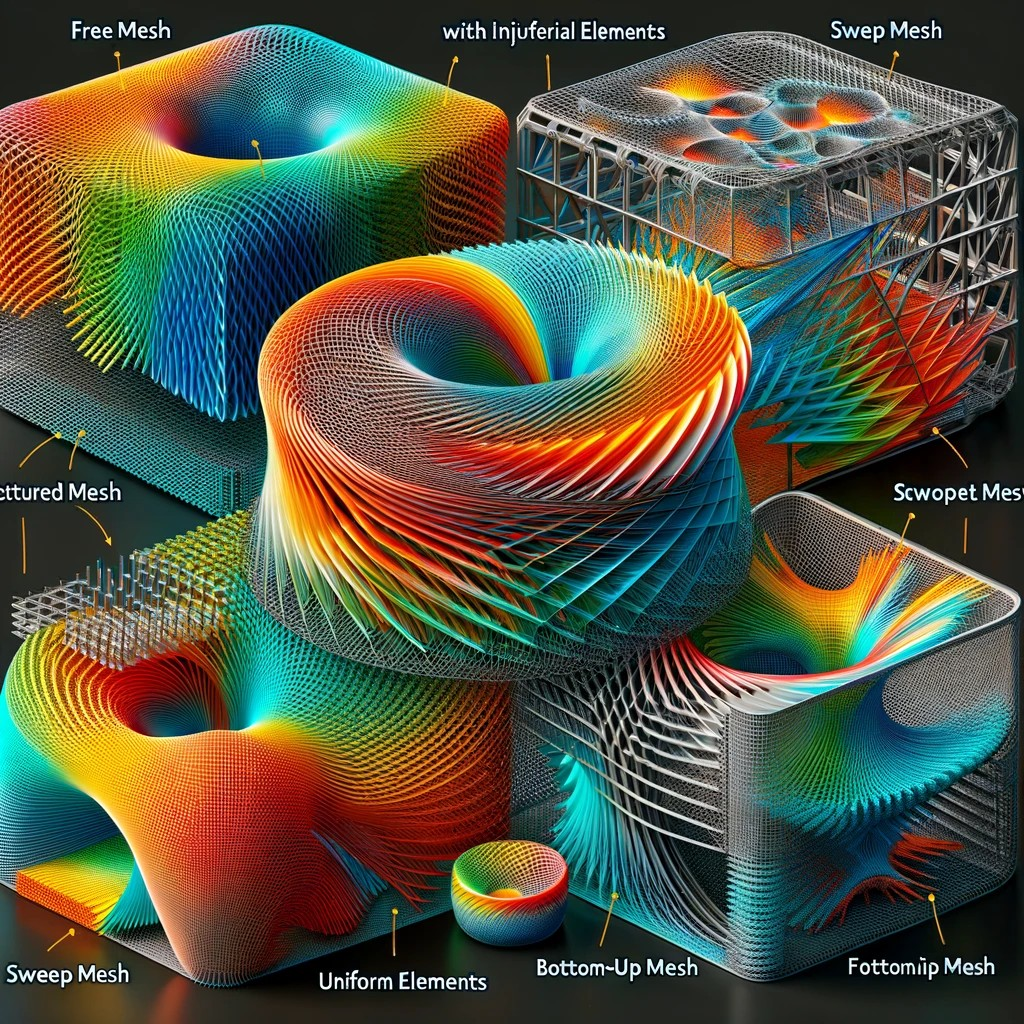
Meshing is a critical component of Finite Element Analysis (FEA), where complex geometries are broken down into smaller, interconnected elements. Simply put, intricate shapes are subdivided into simpler components using finite elements. The accuracy and reliability of an FEA simulation are highly dependent on factors such as mesh size, element type, and element quality. Therefore, understanding how to create an appropriate mesh is essential. In this article, we will explore the different 3D meshing options available in Abaqus CAE, followed by a discussion of key meshing best practices.
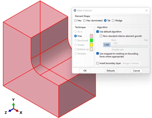
The Mesh module in Abaqus CAE provides all the necessary tools for creating a 3D mesh. Within this module, the geometry is color-coded based on the meshing algorithm chosen for each part. For instance, orange surfaces indicate that the part cannot be meshed automatically. This issue can typically be resolved by adjusting the geometry, partitioning surfaces, or changing the desired element type.

The other mesh-based surface colors present in Abaqus CAE are pink (Free Mesh), green, (Structured Mesh), yellow (Sweep Mesh), and Tan (Bottom-Up Mesh), which will be discussed in more detail in the following sections.
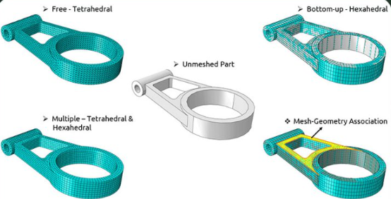
Free Mesh (Unstructured): The Free Mesh algorithm, which is indicated by a pink surface color, is likely the most versatile mesh available in Abaqus CAE. This method uses an unstructured approach to fill a solid void with elements and does not require that they be regular or uniform in size. This meshing approach is sometimes the only option, especially for geometries with highly complex shapes. An example of a tetrahedral Free Mesh is shown below (note the inconsistent mesh through the cross-section).
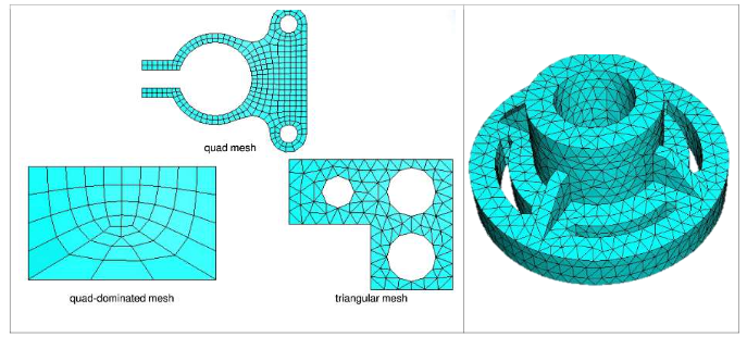
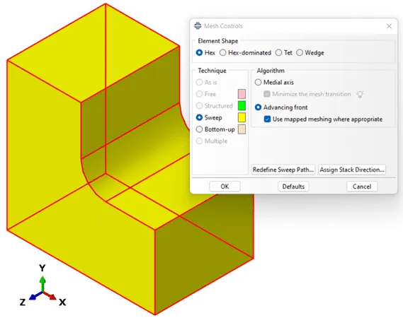
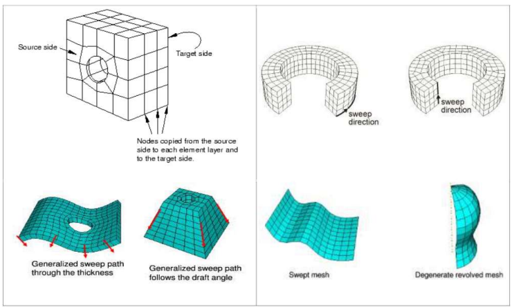
Sweep Mesh: The Sweep Mesh algorithm can be identified by a yellow surface color and provides a convenient method for modeling extruded or revolved parts. This approach provides a much more consistent mesh than Free Meshing since it essentially projects a 2D mesh along a path in 3D space; this results in an evenly distributed, layered mesh across the entire part. An example of a hexahedral Sweep Mesh is shown below (note the consistent, layered mesh through the cross-section).
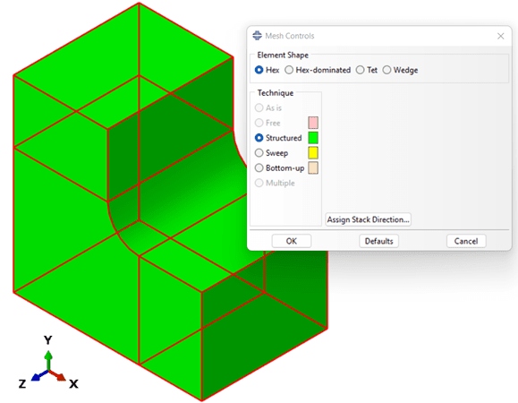
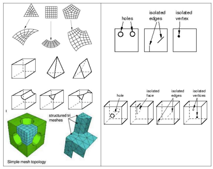
Structured Mesh: The meshing technique that typically provides the highest quality mesh is the Structured Mesh algorithm. This approach is denoted by green surfaces and can only be used on components that can be meshed with consistently sized and shaped elements. This approach is only available when the geometry is partitioned into “regular” shapes (cuboids, cylinders, etc.) and the biggest advantage to using this algorithm is that structured meshing can produce consistent, high-quality mesh. However, since structured meshing requires the elements to be arranged in a regular pattern, this option is often only available when complex geometric surfaces are manually partitioned into regular shapes (rectangles, circles, etc.).
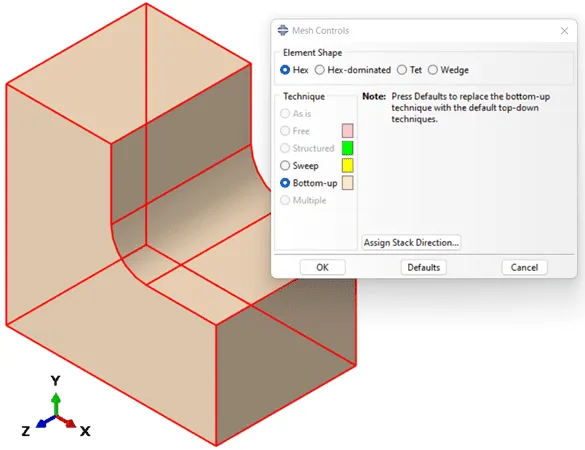
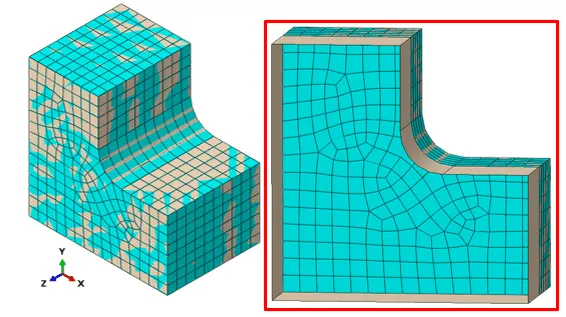
Bottom-Up Mesh: In addition to the automatic meshing techniques previously discussed, Abaqus CAE offers a manual meshing option that provides users with more control over the quality of the mesh. This algorithm, referred to as Bottom-Up Meshing, can be identified by a tan surface color and offers a robust method for generating hexahedral meshes. Because this incremental meshing style uses elements that are not inherently tied to the geometry, this approach offers more versatility than the automatic meshing algorithms when it comes to modeling complex geometry.
Key considerations for meshing include:
Element Type: Choosing the right element type is critical. For instance, fully integrated hexahedral elements can cause shear locking in bending, while incompatible mode elements might lead to convergence issues.
Element Size: Mesh size affects stress analysis accuracy, particularly in regions with high stress gradients. Large elements tend to underpredict stress, so a mesh sensitivity study is essential.
Mesh Quality: High-quality mesh consists of well-shaped, well-connected, and uniform elements. Quality can be assessed using built-in checks in Abaqus CAE.
Best Practices in Meshing
To ensure accurate FEA results, it’s vital to follow best meshing practices such as using structured elements where possible, conducting mesh sensitivity studies, and regularly assessing mesh quality. This approach helps to improve both the reliability and efficiency of simulations.

If you need further assistance with meshing, Abaqus CAE, or any other FEA-related topics, feel free to contact us!
Subscribe to my newsletter
Read articles from Vishal Sharma directly inside your inbox. Subscribe to the newsletter, and don't miss out.
Written by

Vishal Sharma
Vishal Sharma
I hold a Master's degree in Mechanical Design from BITS Pilani, a prestigious institution renowned for engineering. Over the years, my journey has taken me through various pivotal roles that enriched my technical expertise and broadened my perspective on the industry. I started with New Product Development, delving deep into the intricate nuances of product creation from scratch. As an FEA engineer, I had the privilege to leverage software tools like Ansys and Hypermesh, allowing me to comprehend the depths of Finite Element Analysis and Computational Fluid Dynamics. Beyond these roles, my passion for teaching led me to become an Associate Instructor at Skill Vertex, and since 2018, I've been actively educating a growing audience on YouTube. My proficiency doesn't just lie in theoretical knowledge but extends to practical software skills as well, with hands-on experience in CATIA, SolidWorks, and Tolerance Stack-Up Analysis. One of my notable achievements includes the research and design of differential assembly and driveline components, which was a testament to my dedication and knack for mechanical designing. But at the core of it all, my true desire is to share. I want to bridge the gap between academia and industry by spreading professional knowledge on FEA, 3D modeling software, and tolerance stack-up analysis. I believe in empowering the next generation of engineers with not just knowledge but the wisdom of experience.