[Cisco SD-WAN] Centralized Control Policy - Hub-Spoke topology scenarios
 Nam Nguyen
Introduction
In this article, we will learn how the Centralized Control Policy works through a demonstration and guidelines.
Hub and Spoke is a common topology worldwide. By leveraging the separated service VPNs feature in Cisco SD-WAN, multiple types of topologies can be deployed per VPN.
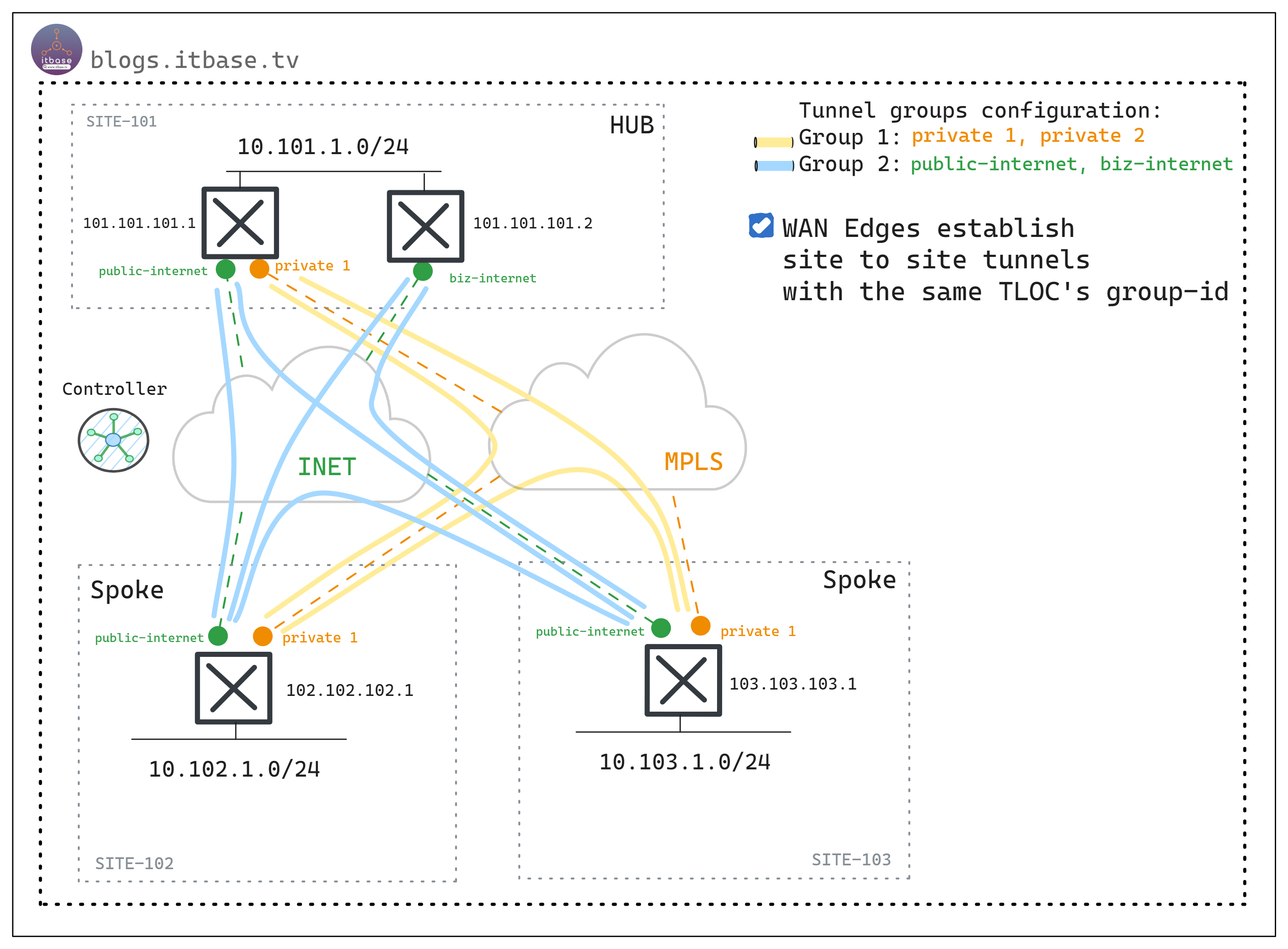
Figure-1. Overview example of demonstration
Referring to Figure-1, this article will describe two examples of Hub-Spoke topology using Centralized Control Policy. Note that, in this example, I configure the tunnel group-id to achieve the public color tunnels separated from private color tunnels.
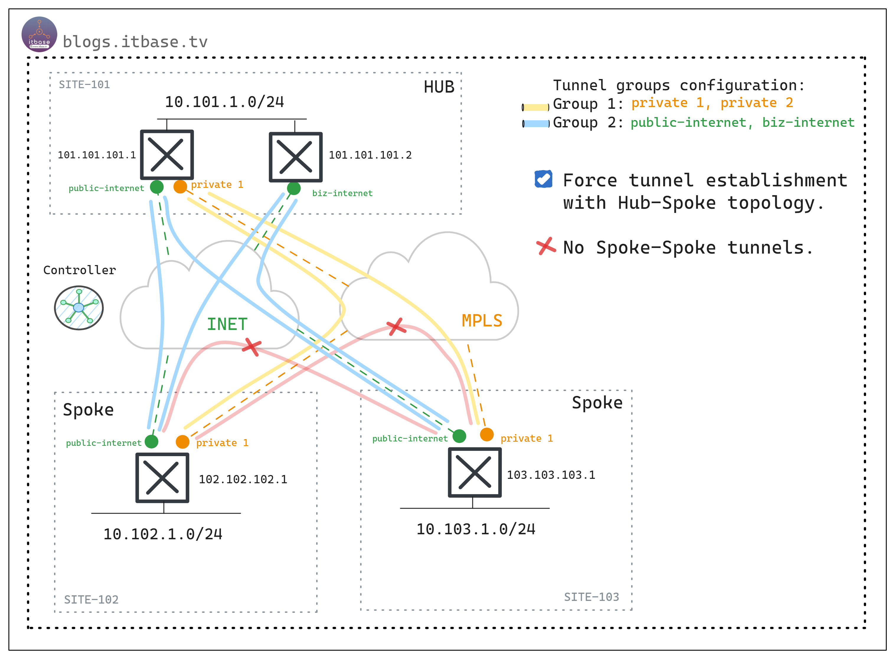
Figure-2. Hub-Spoke topology establishment
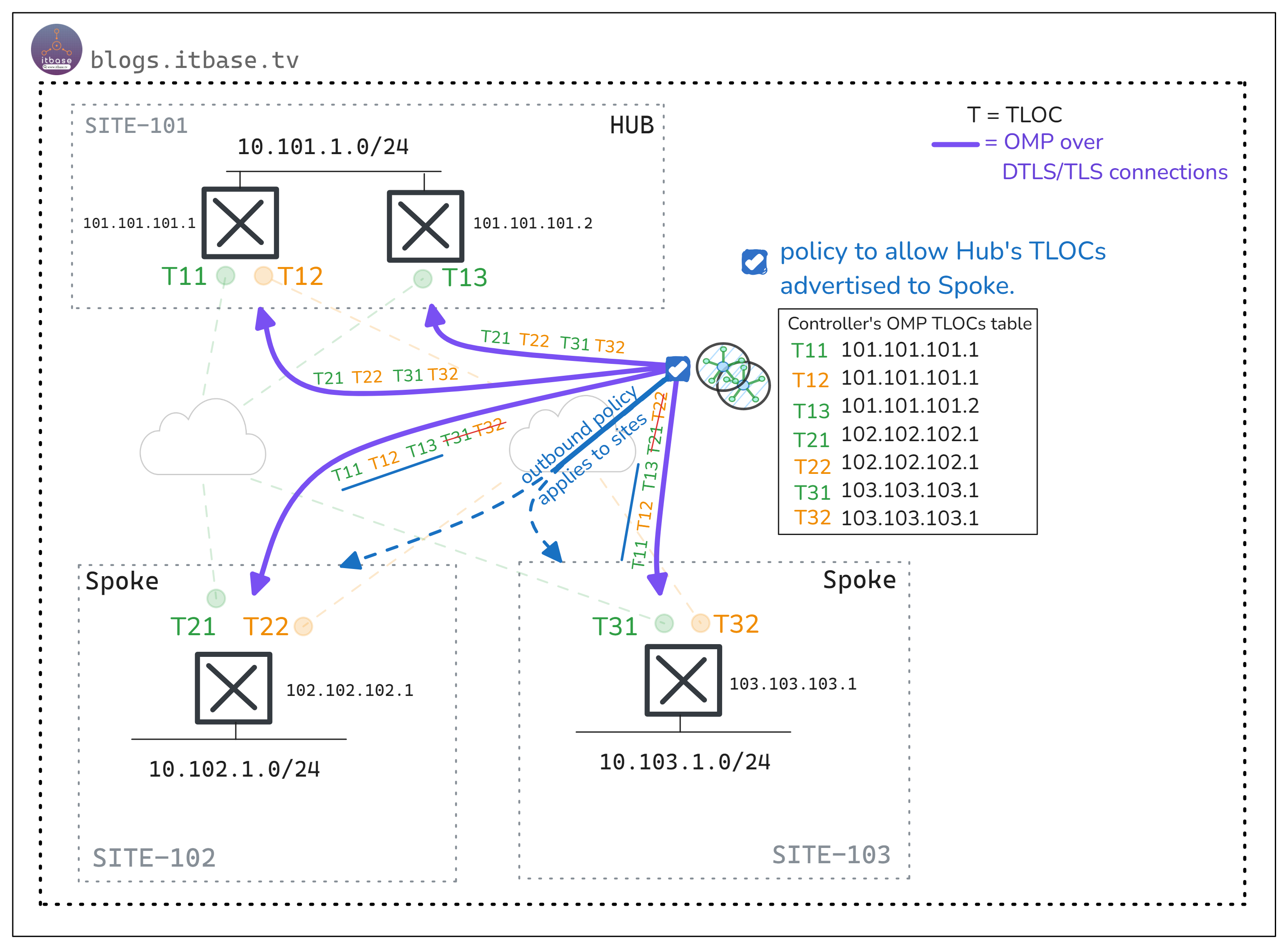
Figure 2 shows that data plane tunnels will not be established between the Spoke sites. By using the Centralized Control Policy (Figure 3), I will allow only the Hub's TLOCs to communicate with the Spoke sites. This way, the Spokes cannot learn each other's TLOC information.
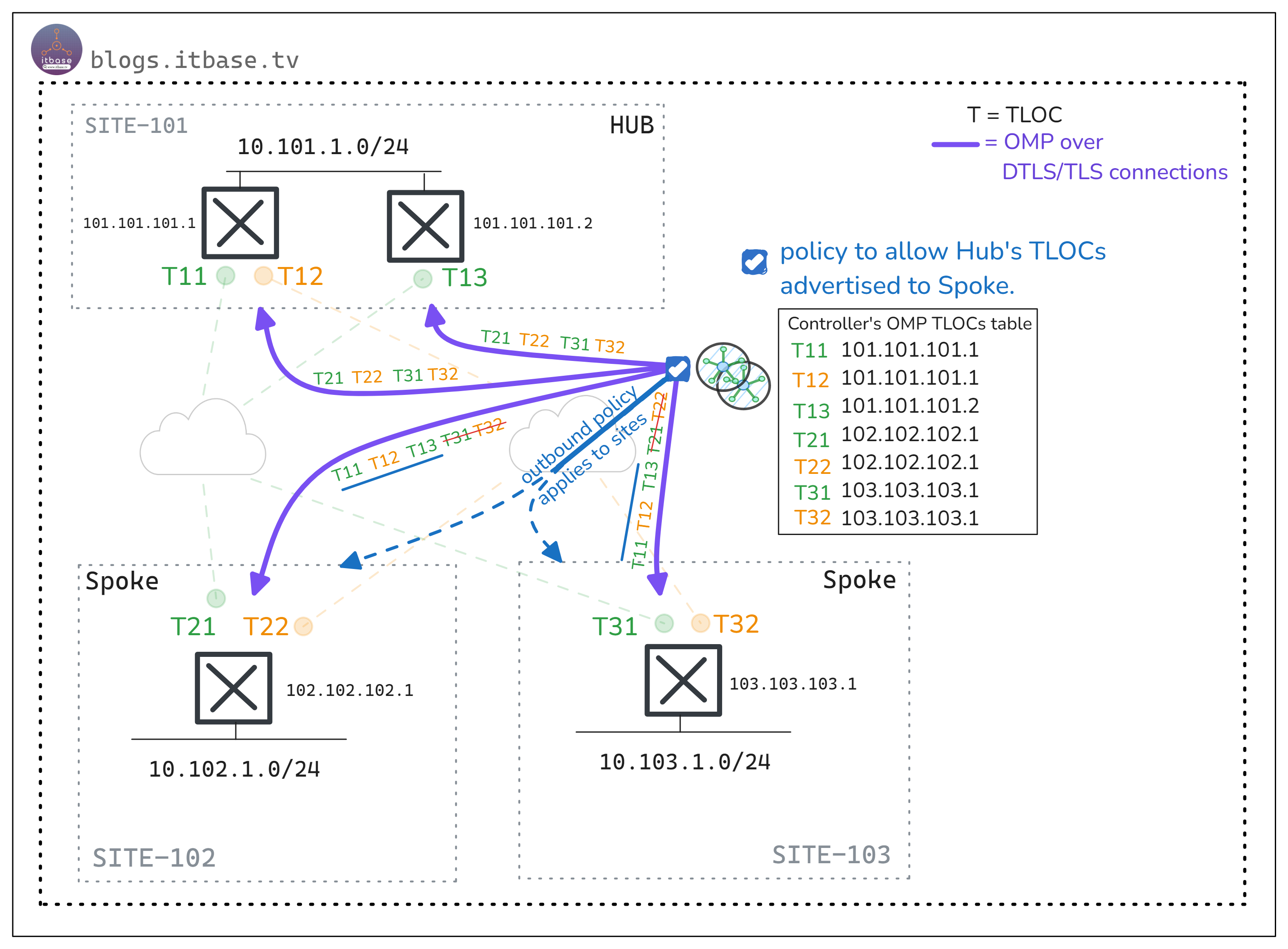
Figure-3. Centralized control policy is applied to Controllers.
Using this topology example, I will demonstrate two scenarios below:
In Scenario 1, Spoke sites (site 102, site 103) will establish data plane tunnels (IPSec) with the Hub site (site 101), and the Spokes will not communicate with each other.
In Scenario 2, similar to Scenario 1 excepting the Spokes will be able to communicate with each other through the Hub site.
Before go to details, let me explain how I naming the router hostname / ip address / system ip, etc.
Site ID: 101, 102, 103
System IP: 101.101.101.x (3 octets will use site id and last octet will the router number at site, for example, site 101 have two WAN Edges, so I will use system ip as 101.101.101.1 and 101.101.101.2)
Hostname: WAN Edge Router = WER-1011 (101 = site-id, 1 = router number at site)
LAN segments: 10.101.1.0/24 (101 = site-id), the site id will be the 2nd octet.
Service VPN: I use single service VPN in this article (VPN 1000)
Scenario 1: Hub-Spoke tunnels without Spoke-Spoke communication
Preview
By default, Controllers (vSmart) will receive and advertise all of TLOC routes to all site (101, 102, 103) using OMP.
Let’s check the WER-1021 (site 102) and WER-1031 (site 103) OMP TLOC tables by default as below
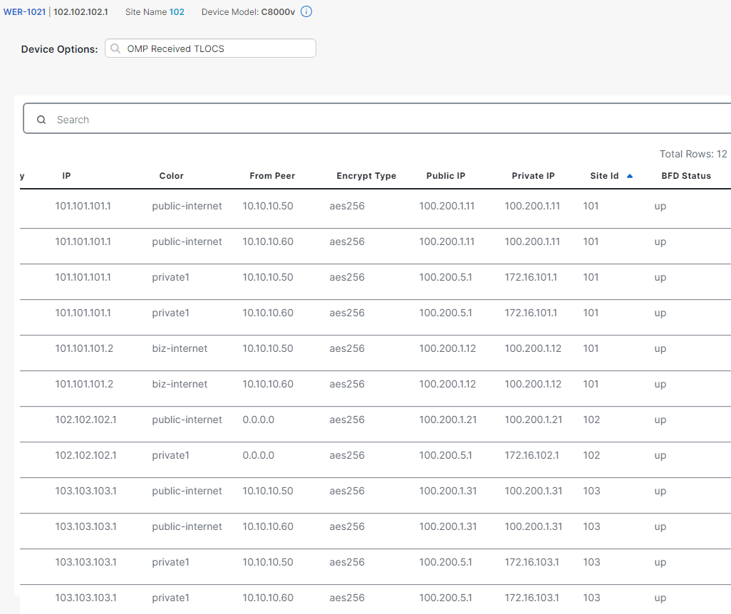
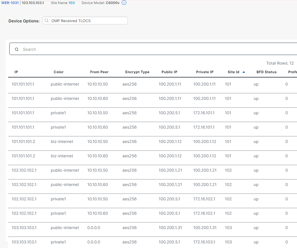
At the Site Id column, we can see Controller advertises fully TLOCs to these sites.
From site 102, WER receives TLOCs from site 101 and 103, so the full-mesh tunnels (among sites) are established.
How about OMP routes table? Let check below
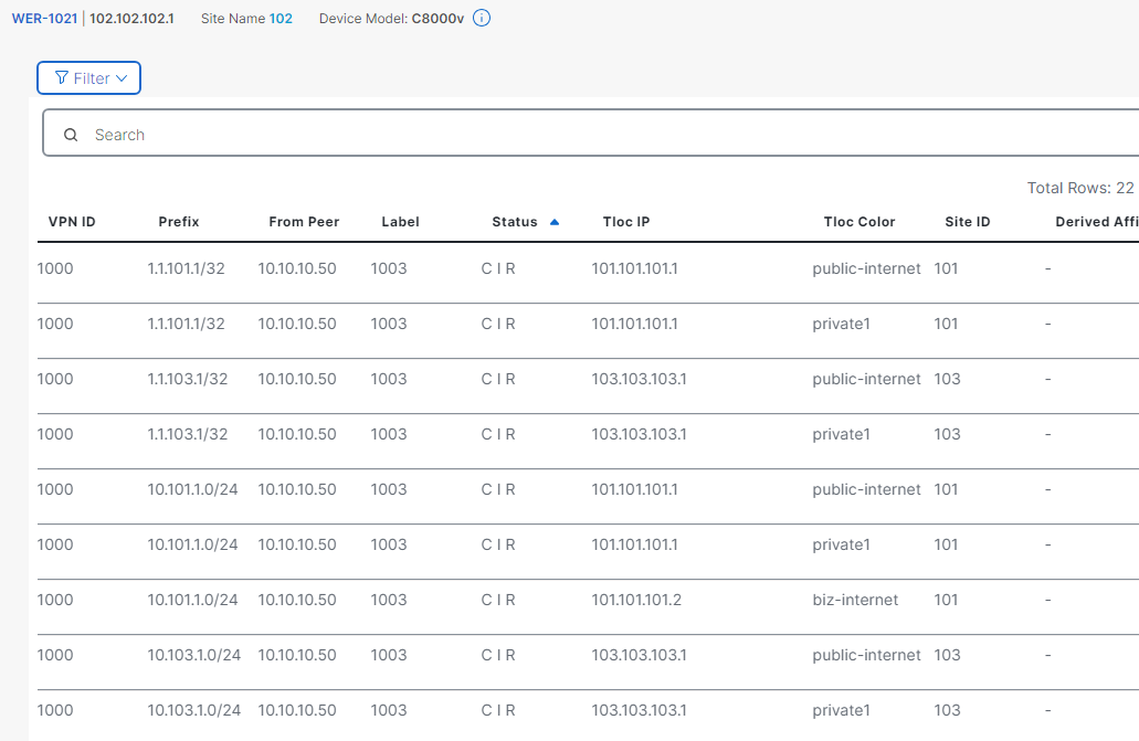
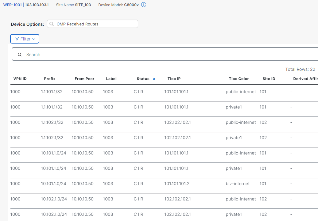
The WER-1021 (site 102) receives the OMP LAN routes originated from site 101, and 102. Similar to WER-1021, the WER-1031 (site 103) receives the OMP LAN routes from site 101 and site 102.
Policy Implementation
By using these below steps, we can implement the Centralized Policy:
Step 1: Define the list of interest. (site list, VPN list, etc)
!
 lists
  site-list hub-sites-list
   site-id 101
  !
  site-list spoke-sites-list
   site-id 102
   site-id 103
  !
  vpn-list VPN1000
   vpn 1000
  !
 !
!
Step 2: Create control policy using structure match-action.
The sequence will be read from smallest to largest, and each sequence will include the match (condition) and action phases (do something if condition is matched).
viptela-policy:policy
 control-policy HUB-SPOKE-cp
    sequence 10
     match route
      site-list hub-sites-list
      vpn-list VPN1000
     !
     action accept
     !
    !
    sequence 20
     match tloc
      site-list hub-sites-list
     !
     action accept
     !
    !
  default-action reject
 !
In sequence 10, the “match route” condition means all of OMP routes originated from hub-sites-list (site 101) AND these routes belong to VPN 1000. Action accept shows that the Controller will allow matched routes to be advertised to the applied target sites. (at step 3).
In sequence 20, the “match tloc” condition means all the TLOC routes originated from hub-sites-list (site 101) will be accepted to be advertised to target sites.
Default-action reject, it means all of routes which do not match any condition will be rejected to be advertised to target sites.
Step 3: Apply policy to the list of sites (Spokes)
Apply policy to the list of sites (Spokes) with outbound direction on Controller. The centralized control policy will be pushed to Controller (vSmart) after activating, all of in / out TLOC/OMP routes will go through these control policy before distributing to sites in fabric.
apply-policy
 site-list spoke-sites-list
  control-policy HUB-SPOKE-cp out
 !
!
In summary, the OMP routes and TLOC routes from HUB site (101) will be advertised to Spokes (site 102, 103). And OMP/TLOC routes from site 102 will be rejected to advertise to site 103 and vice versa.
Verify
The TLOC route table on Spokes site will not receive any Spoke's TLOC anymore.
The OMP routes table on WER-1021 will not display the LAN routes originated from Spokes (site 103) any more and vice versa.
Let’s verify the result by traceroute from WER-1021 (spoke) to 10.101.1.1 (Hub’s LAN).
The below output show reachability to Hub site from Spoke site.
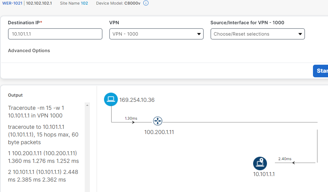
Let’s try to check connection from Spoke (102) to Spoke (103) as below Figure.
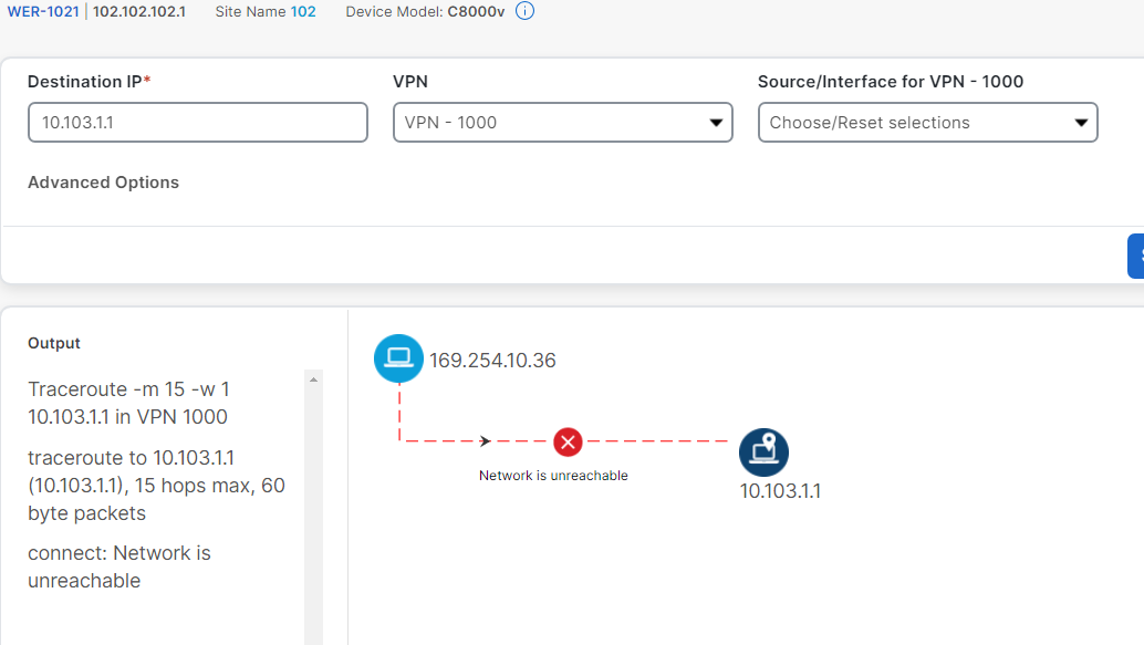
Great! The result is unreachable as our expectation.
The Scenario 2 will be released soon.
Subscribe to my newsletter
Read articles from Nam Nguyen directly inside your inbox. Subscribe to the newsletter, and don't miss out.
Written by

Nam Nguyen
Nam Nguyen
Visit to see more: https://linktr.ee/nddnam I am an enthusiastic Network Engineer with 7+ years of experience working on MPLS L3VPN Network projects, Cisco SDWAN Deployment, and Enterprise Networks. I love to automate every daily task and think Dev-Ops as always. Thus, I am entering the DevNet world.


