How to Use Switch Case in Arduino – Control LEDs With the Switch Statement
 Ihechikara Abba
You can use a switch case statement to execute different blocks of code based on the value of a variable. It offers a more direct and cleaner approach to handling multiple conditions.
In this article, you'll learn how to control LEDs using a switch case statement in Arduino. You can also find the switch case statement in other programming languages, so this can serve as a practical example of how they work.
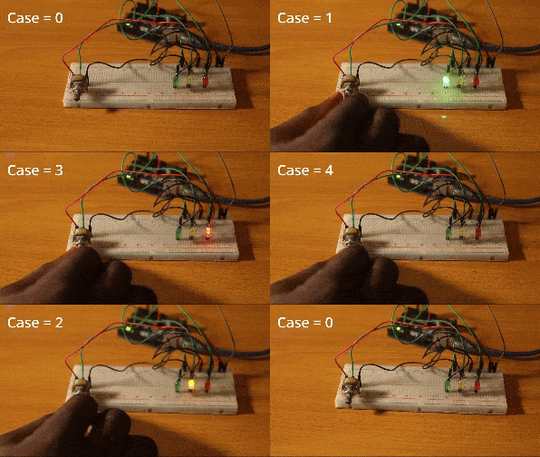
Here’s a demo of what you’ll be building:

You can watch the video version of this article here:
Hardware Components
Here are the components you'll need to follow along:
Arduino board (Uno).
Potentiometer.
Breadboard.
Three LEDs.
Resistors for the LEDs.
Jumper wires.
How to Use a Switch Case Statement in Arduino
Here's the syntax/structure of a switch statement:
switch (variable) {
  case value1:
    // code to be executed if variable == value1
    break;
  case value2:
    // code to be executed if variable == value2
    break;
  default:
    // code to be executed if variable doesn't match any case
    break;
}
Let's break it down:
variable: This denotes the variable being evaluated. The value of the variable determines how the code blocks will be executed.case: Eachcaserepresents a value that may match the variable being evaluated. If thevariableand acasehave the same value, the code for that case will be executed. You can have as many cases as you want.break: After a code block in acasehas been executed, thebreakkeyword terminates the code. That is, it stops the code from moving on to other cases because a match has already been found.default: In a situation where none of the cases match thevariable, the code in thedefaultblock will be executed.
Next, let's use a switch statement to control LEDs.
Switch Case in Arduino Example
Circuit Diagram
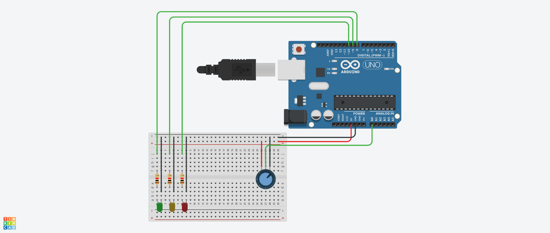
Here’s how to connect your components:

The goal here is to decide which LED (or a combination of LEDs) comes on based on the value of a variable.
Potentiometer Connection
Connect the left terminal of the potentiometer to 5V.
Connect the right terminal to GND.
Connect the middle terminal to A0.
LED Connection
For each LED, connect the shorter leg to GND.
Connect each longer leg to a digital pin. I recommend using pin 8 (for the green LED), 9 (for the yellow LED), and 10 (for the red LED) to match what we have in the circuit diagram. We'll also use these values in the code.
Here's the full project code:
int greenLED = 8;
int yellowLED = 9;
int redLED = 10;
int potPin = A0;
int potValue;
int mappedPotValue;
void setup() {
  pinMode(greenLED, OUTPUT);
  pinMode(yellowLED, OUTPUT);
  pinMode(redLED, OUTPUT);
  Serial.begin(9600);
}
void loop() {
potValue = analogRead(potPin);
mappedPotValue = map(potValue, 0, 1023, 0, 5);
  switch (mappedPotValue) {
    case 0:
      digitalWrite(greenLED, LOW);
      digitalWrite(yellowLED, LOW);
      digitalWrite(redLED, LOW);
      Serial.println(mappedPotValue);
      break;
    case 1:
      digitalWrite(greenLED, HIGH);
      digitalWrite(yellowLED, LOW);
      digitalWrite(redLED, LOW);
      Serial.println(mappedPotValue);
      break;
    case 2:
      digitalWrite(greenLED, LOW);
      digitalWrite(yellowLED, HIGH);
      digitalWrite(redLED, LOW);
      Serial.println(mappedPotValue);
      break;
    case 3:
      digitalWrite(greenLED, LOW);
      digitalWrite(yellowLED, LOW);
      digitalWrite(redLED, HIGH);
      Serial.println(mappedPotValue);
      break;
    case 4:
      digitalWrite(greenLED, HIGH);
      digitalWrite(yellowLED, HIGH);
      digitalWrite(redLED, HIGH);
      Serial.println(mappedPotValue);
      delay(500);
      digitalWrite(greenLED, LOW);
      digitalWrite(yellowLED, LOW);
      digitalWrite(redLED, LOW);
      Serial.println(mappedPotValue);
      delay(500);
      break;
  }
}
Let's break down the code.
Variable Initialization
int greenLED = 8;
int yellowLED = 9;
int redLED = 10;
int potPin = A0;
int potValue;
int mappedPotValue;
We started by initializing variables to correspond with the hardware connections.
greenLED, yellowLED, and redLED have values of 8, 9, and 10, respectively. This matches the pins they were connected to on the Arduino board. Similarly, potPin, which is the variable for the potentiometer, has a value of A0.
You'll use the potValue variable to store the current value of the potentiometer. We also created a mappedPotValue variable to store the range of values needed for the LEDs in a minute.
pinMode and Serial Monitor
void setup() {
pinMode(greenLED, OUTPUT);
pinMode(yellowLED, OUTPUT);
pinMode(redLED, OUTPUT);
Serial.begin(9600);
}
In the setup() function, we set the LEDs as output pins and initialized the serial monitor.
Logic for switch case Statement
First, we read the value of the potentiometer using the analogRead() function and stored it in the potValue variable:
potValue = analogRead(potPin);
We then converted the values from the potentiometer to a range of 0 to 4 using the map function and stored them in the mappedPotValue variable:
mappedPotValue = map(potValue, 0, 1023, 0, 5);
Next, we created a switch statement—the value being evaluated is mappedPotValue. Recall that this is the variable where we stored the potentiometer values. So whenever you turn the potentiometer, the value changes and potentially matches a case:
switch (mappedPotValue) {
case 0:
digitalWrite(greenLED, LOW);
digitalWrite(yellowLED, LOW);
digitalWrite(redLED, LOW);
Serial.println(mappedPotValue);
break;
case 1:
digitalWrite(greenLED, HIGH);
digitalWrite(yellowLED, LOW);
digitalWrite(redLED, LOW);
Serial.println(mappedPotValue);
break;
case 2:
digitalWrite(greenLED, LOW);
digitalWrite(yellowLED, HIGH);
digitalWrite(redLED, LOW);
Serial.println(mappedPotValue);
break;
case 3:
digitalWrite(greenLED, LOW);
digitalWrite(yellowLED, LOW);
digitalWrite(redLED, HIGH);
Serial.println(mappedPotValue);
break;
case 4:
digitalWrite(greenLED, HIGH);
digitalWrite(yellowLED, HIGH);
digitalWrite(redLED, HIGH);
Serial.println(mappedPotValue);
delay(500);
digitalWrite(greenLED, LOW);
digitalWrite(yellowLED, LOW);
digitalWrite(redLED, LOW);
Serial.println(mappedPotValue);
delay(500);
break;
}
We passed mappedPotValue as a parameter to switch since it's the variable being compared to different cases: switch (mappedPotValue).
For
case 0, all the LEDs will be off.For
case 1, only the green LED comes on.For
case 2, only the yellow LED comes on.For
case 3, only the red LED comes on.For
case 4, all three LEDs will blink continuously.
Using a switch statement, you've successfully controlled the behavior of LEDs based on the value of a potentiometer!
Conclusion
In this article, you learned how to use a switch case statement in Arduino using a practical example.
You learned how to control different LEDs based on the value of a potentiometer. You achieved this by using different cases in a switch statement to match the potentiometer's current value and execute the corresponding code.
switch statements can be used in different ways to make a project more dynamic. Some use cases in Arduino include:
Managing and interpreting the different values, modes, and states of a component or sensor.
Performing actions based on specific commands. For example, rotating a robotic arm to a specific angle/direction.
Mapping button presses to user input, and so on.
You can watch the video version of this project here. The full project code is available on GitHub.
Check out my blog for articles about embedded systems, IoT, and web development.
Happy coding!
Subscribe to my newsletter
Read articles from Ihechikara Abba directly inside your inbox. Subscribe to the newsletter, and don't miss out.
Written by

Ihechikara Abba
Ihechikara Abba
ihechikara.com