Wire Up Your Small Office Home Office: A Techie's Dream Come True
 Elinathan Olotu
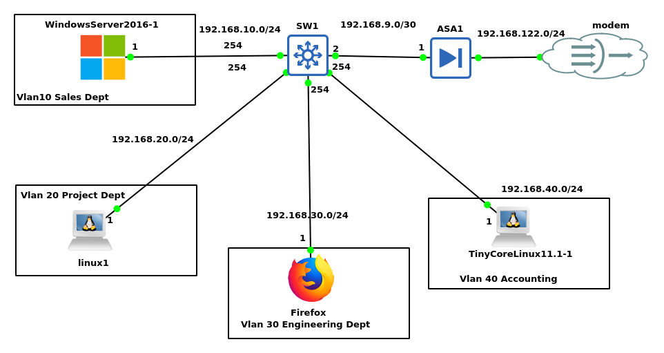
In this blog, I will show you how to build a secure network for your small office home office network.
Prerequisites
I am using the famous GNS3 tool for network engineers, version 2.2.50, in this blog.
Introduction
Want to bridge the gap between theory and practice? This tool lets you experiment with real-world Cisco IOS and firewall commands in a safe, simulated environment. Join us as we explore practical network configurations and troubleshooting techniques, all backed by clear diagrams. In this blog, I will demonstrate how to set up a small office home office network and then get them all to the internet.
Step 1: Use the GNS3 software to Lab it.
GNS3 is a powerful tool requiring sufficient hardware to run smoothly. My Ubuntu Linux 22.04 dual-boot laptop, with its CPU of core i3\ and 8GB of RAM, provides the minimum necessary resources. This is crucial, as network devices can be memory-intensive, especially when simulating large-scale networks.
Then I import the images for the blog into the emulator in the diagram above.
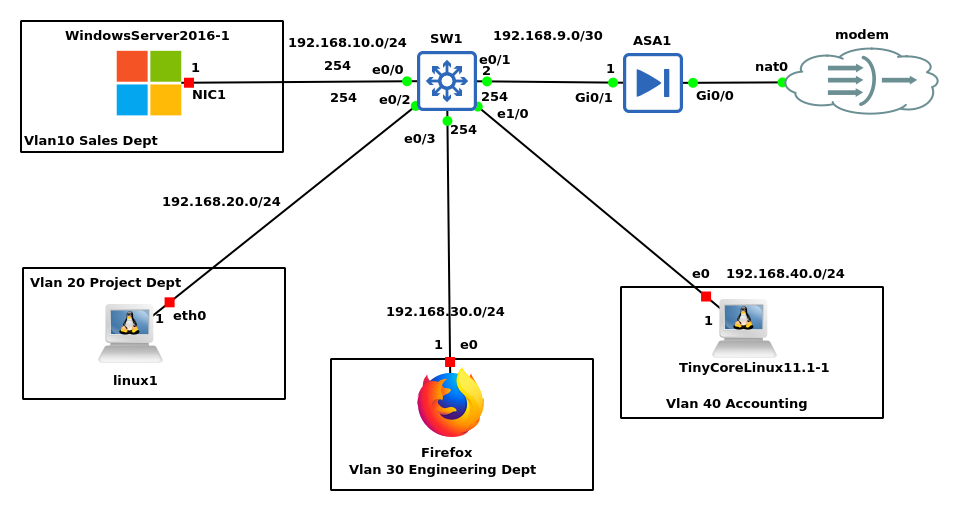
Above is the full topology for the small office home office network design with the wiring included and the IP addressing scheme for the various departments as shown in the diagram.
I used a /24 address mask to incorporate future staff in case of an expansion as shown to allow for scalability and in some cases devices to surf the internet. I put them in separate VLANs to separate their traffic from each other and for easier monitoring and identification when their packets are transiting the Cisco ASA firewall.
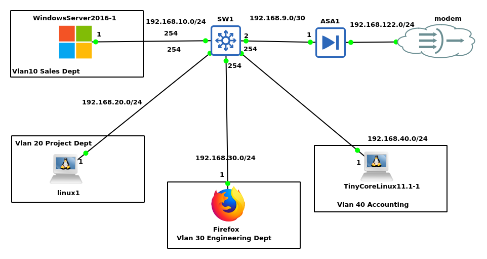
In this lab, as shown in the diagram all the departments are connected to the same switch but are separated on the switch using Vlans and I enabled inter-vlan routing for them to be able to communicate with each other and also the internet as shown below.
Note: in the diagram below the green light indicates it is on while the red light indicates it is off.
Step 2: Lab Configuration
First, I am emulating a real-world scenario where a client wants me to give connectivity to the 4 departments that I named the Vlans after, He wants it secured and the ability to monitor the activities of his staff without using 3rd party monitoring software e.g. SolarWinds.
Also in this lab, the Cisco ASA is emulating the real-world Cisco ASA 5500-x series firewall, while the switch is a Cisco IOU device emulating the real-world catalyst 3750 switch series. The Windows server 2016 emulates the real-world Microsoft server 2016 while the Linux 2 emulates the Linux server platform same as the Firefox and the tiny core Linux. I am using it to emulate the staff’s devices.
I started with the firewall and created the interface to the modem from the service provider, I enabled the interface as per Cisco firewall rules putting the interface in security level 0 as shown below.
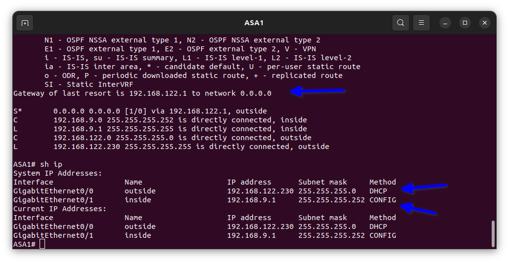
As shown in the diagram below the commands in the Cisco firewall are slightly different from the regular Cisco IOS.
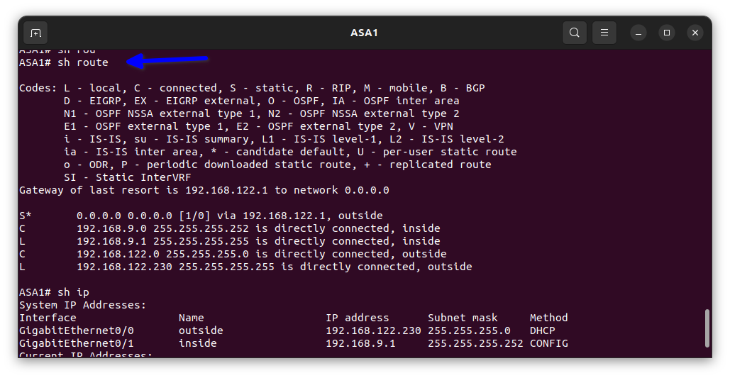
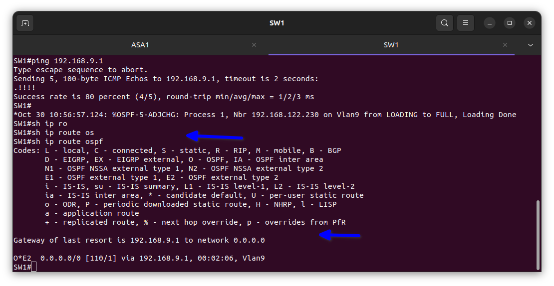
And I put the interface to my company’s network in security level 100 by naming it inside thereby making it very secure. Next, I enabled default routing on the firewall to allow the inside network to access the internet. I also enabled default routing in the routing protocol of OSPF to allow the inside network to browse the internet.
Then I move to the switch that will house all the configuration for the internal network and enable the Vlans there and also configure the interface of the switch to allow the packets through.
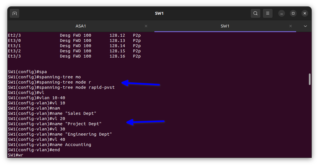
I used a rapid spanning tree for faster convergence and to prevent switching loops that can slow the network down, as shown in the diagram above, and also the Vlans.
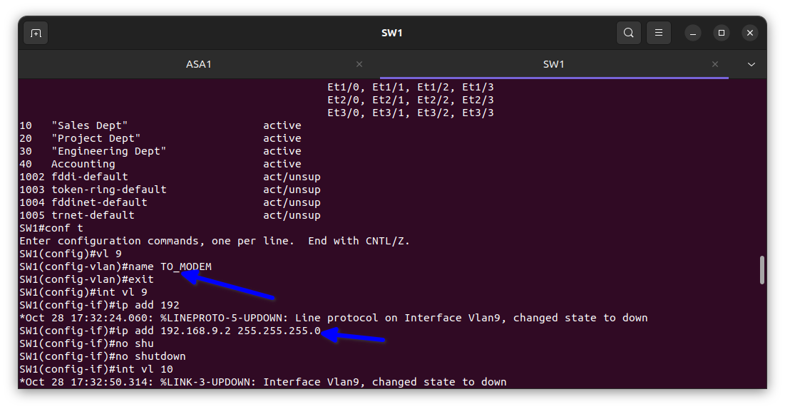
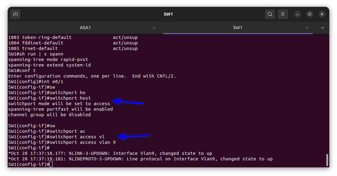
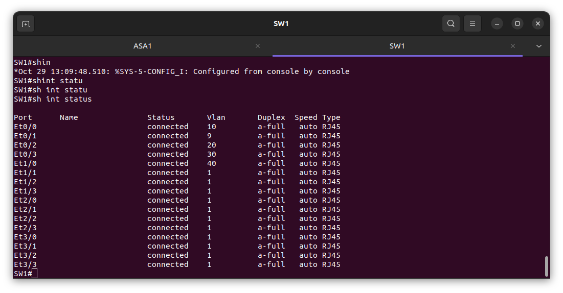
In the diagram above I added the the Vlan to their respective port for the interface on the switch to come up for interconnectivity to take place between the 4 offices that we named the Vlans after.
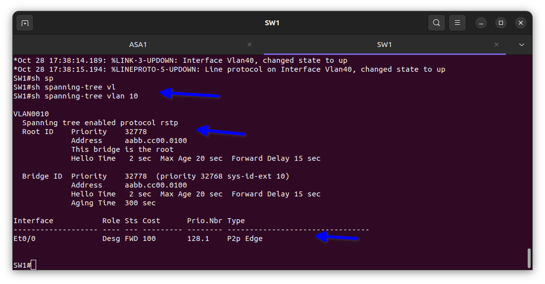
The diagram above indicates that all the packets from the sales dept are passing through.
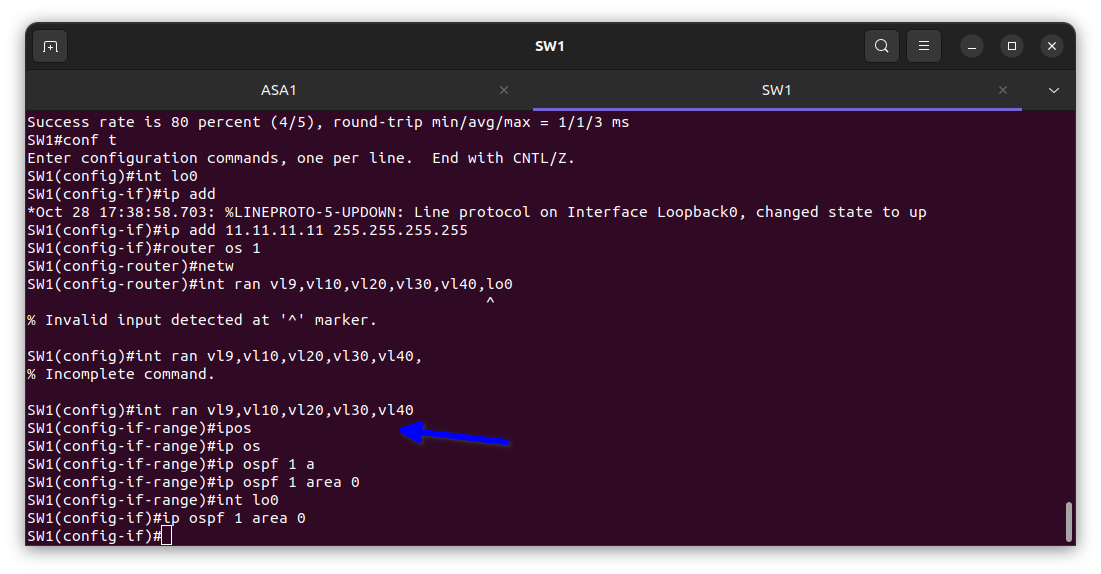
In the diagram above I used the interface range command to add multiple VLAN interfaces at once to save time then enable OSPF routing protocol on them for interconnectivity with each other and the firewall too.
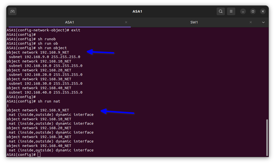
As shown in the diagram below, I enabled NAT in the firewall to use the only IP address the ISP gave us which was 192.168.122.230/24 to enable all the devices in the network to access the internet.
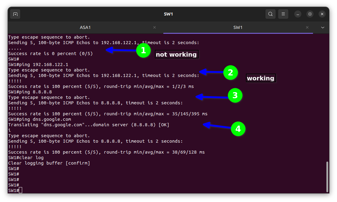
As shown below, item 1 is testing the default gateway while item 3 is testing the DNS to verify it is working, “ ! ” indicating it is working while the dot (.) indicates not working.
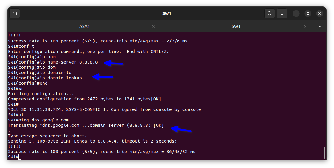
In the diagram below, I configured the DNS on the switch to test it.
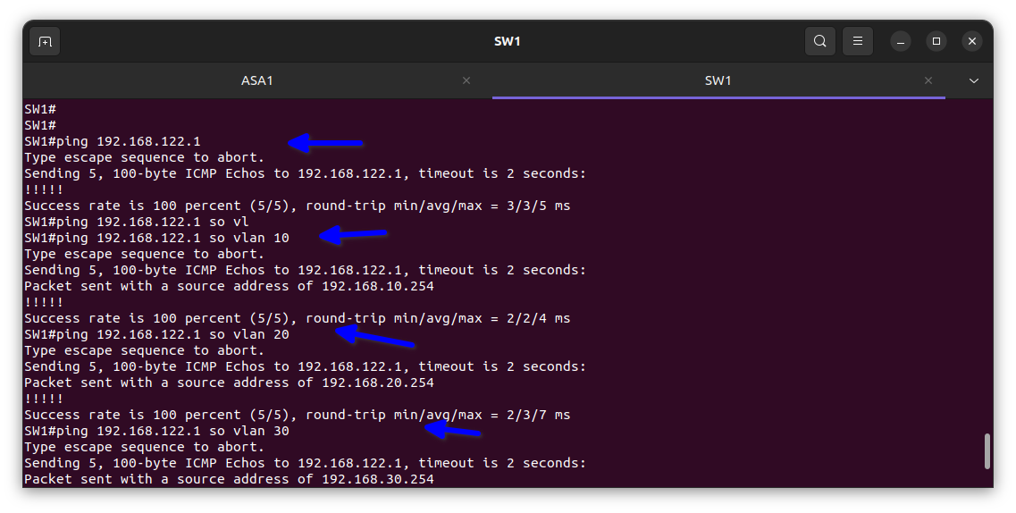
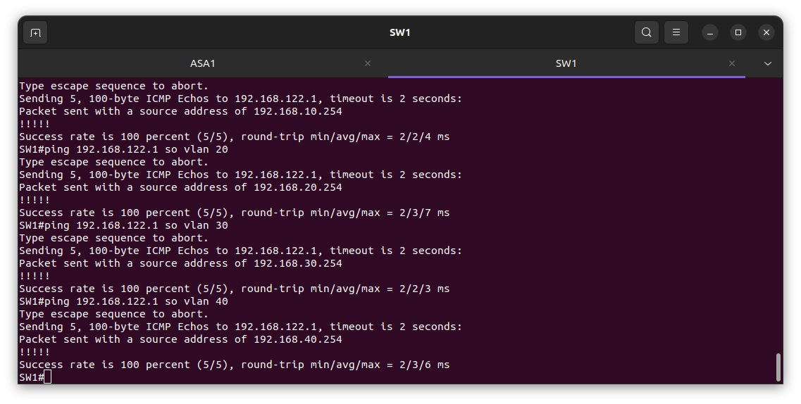
In the diagram above I test the VLANs from the switch to verify it is working.
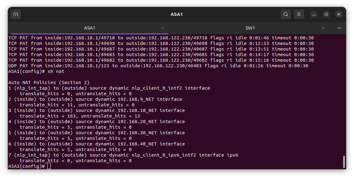
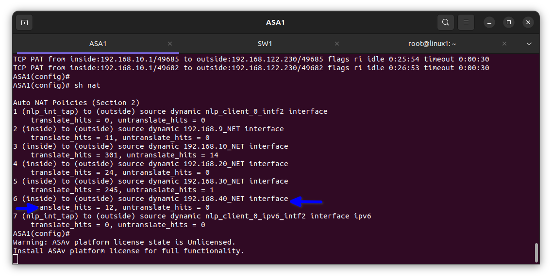
In the diagram below I verified it had been translated into the firewall
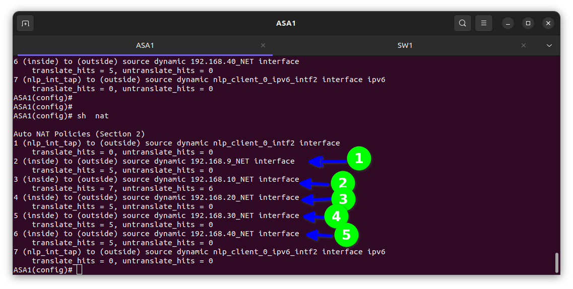
The translate hits = 5 means the private IP address e.g. 192.168. etc in the inside is been translated meaning it’s working and my client’s staff can surf the internet.
Step 3: Verification
For VLAN 10 sales dept
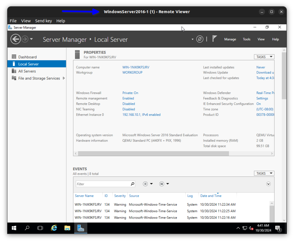
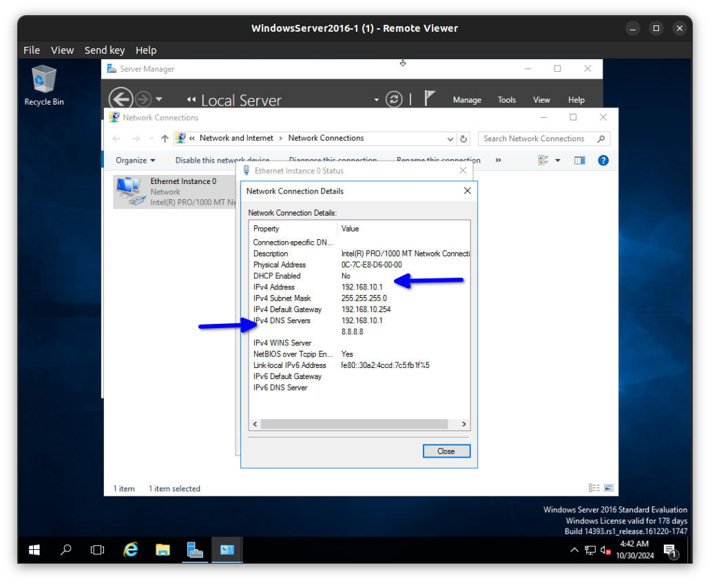
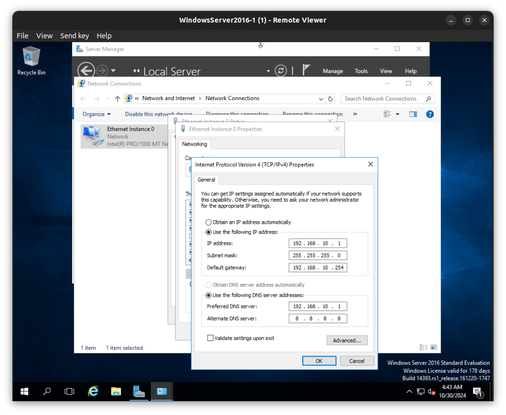
Here it is working.
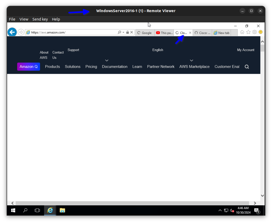
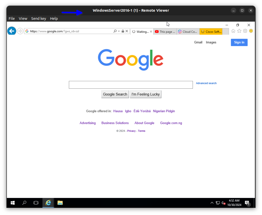
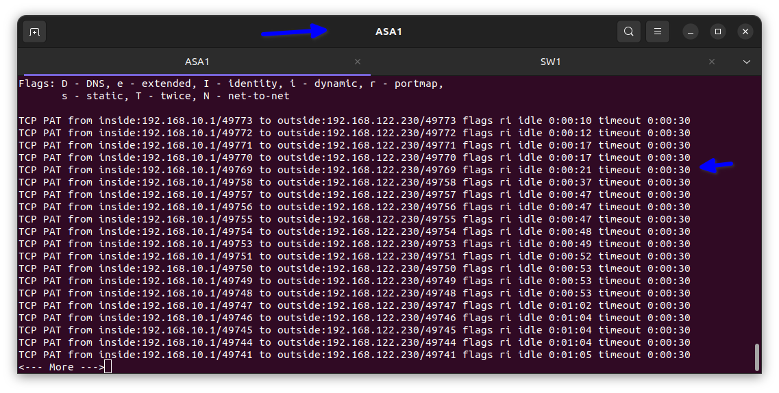
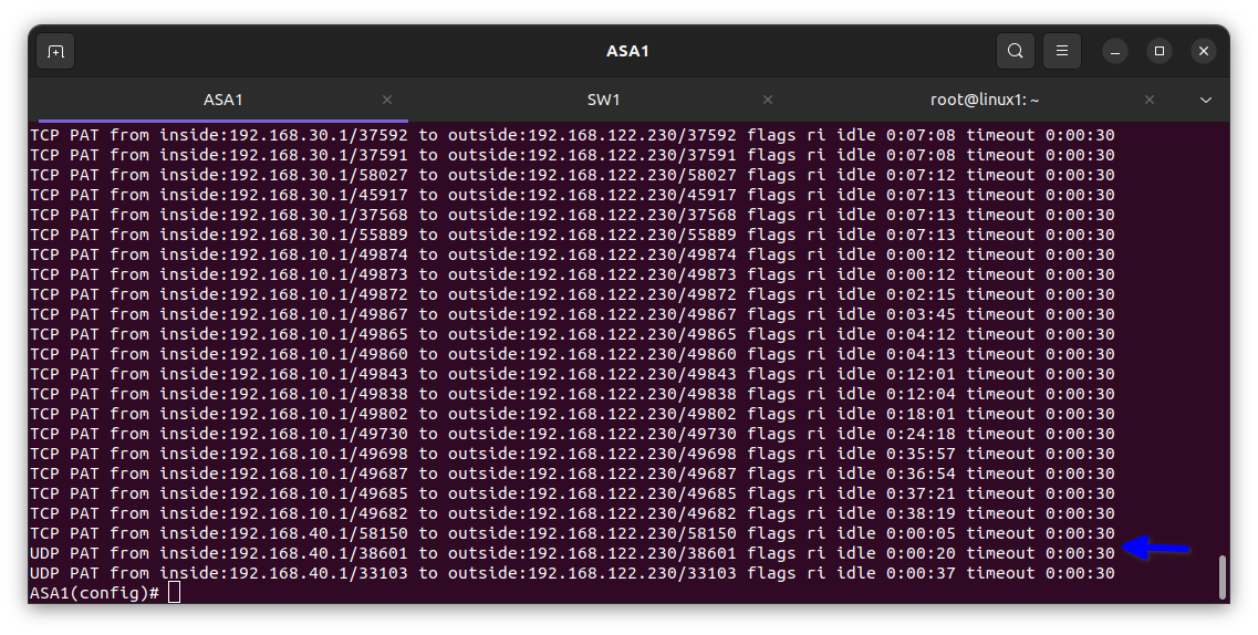
In the diagram below you can see the private IP address has been translated to the ISP address.
For VLAN 20 Project dept
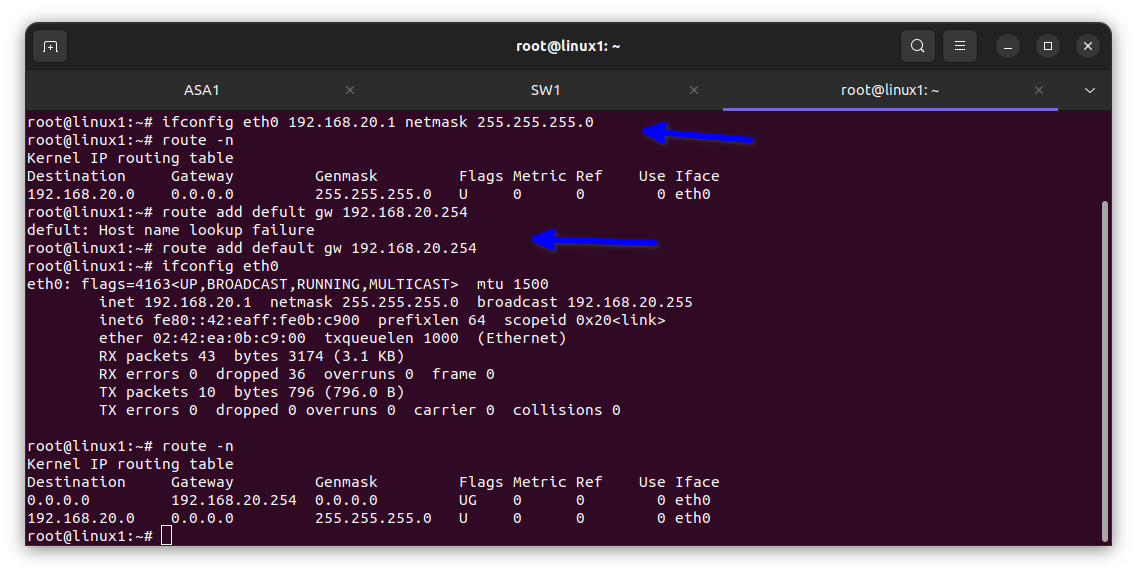
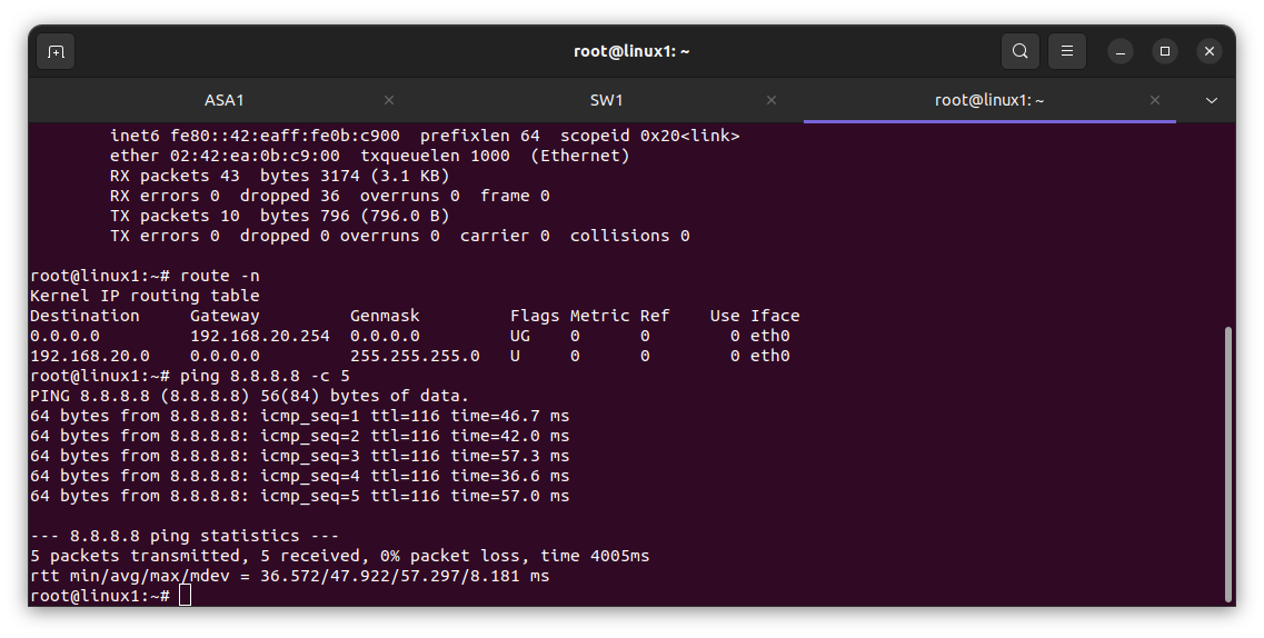
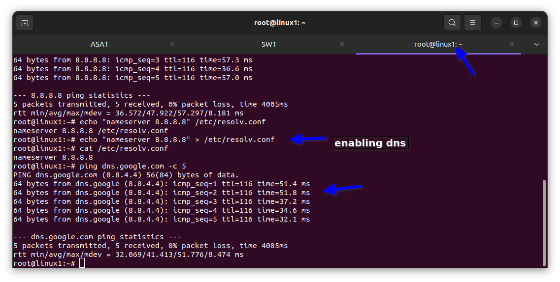
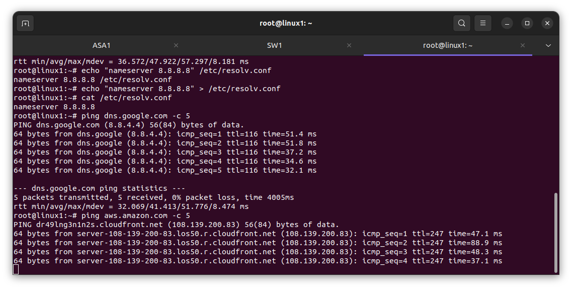
For VLAN 30 Engineering dept
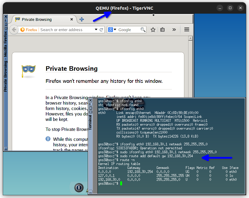
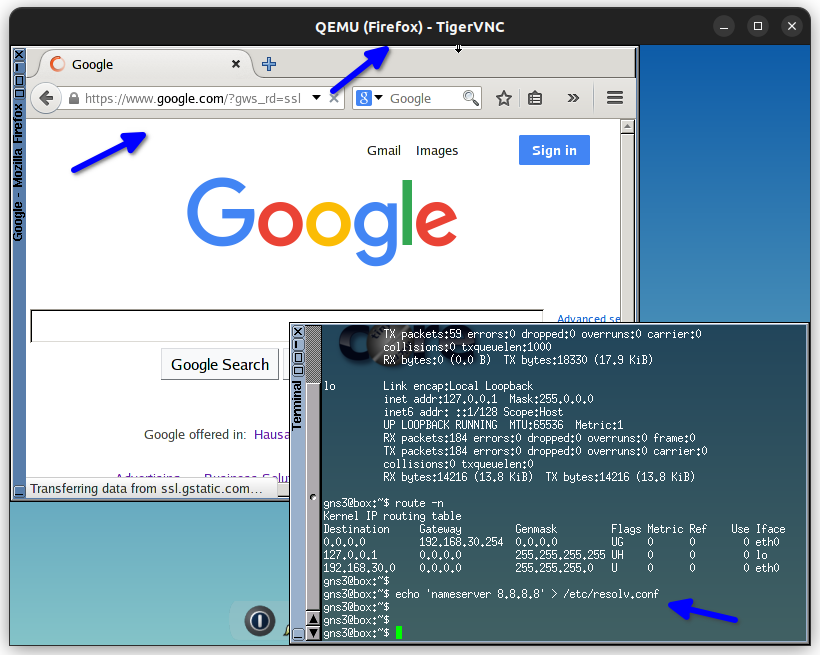
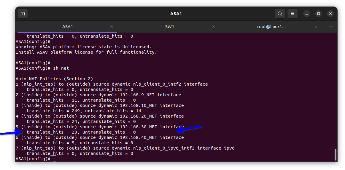
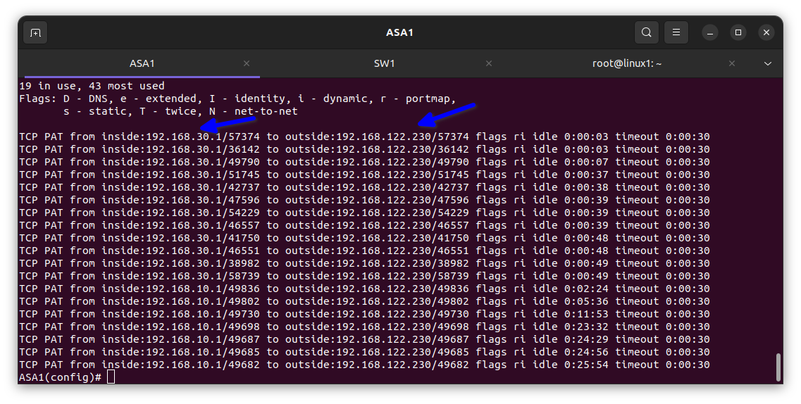
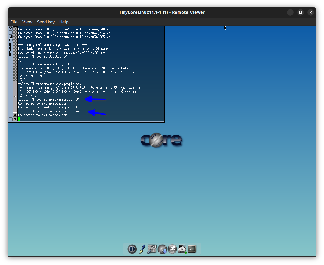
For the VLAN 40 Accounting dept
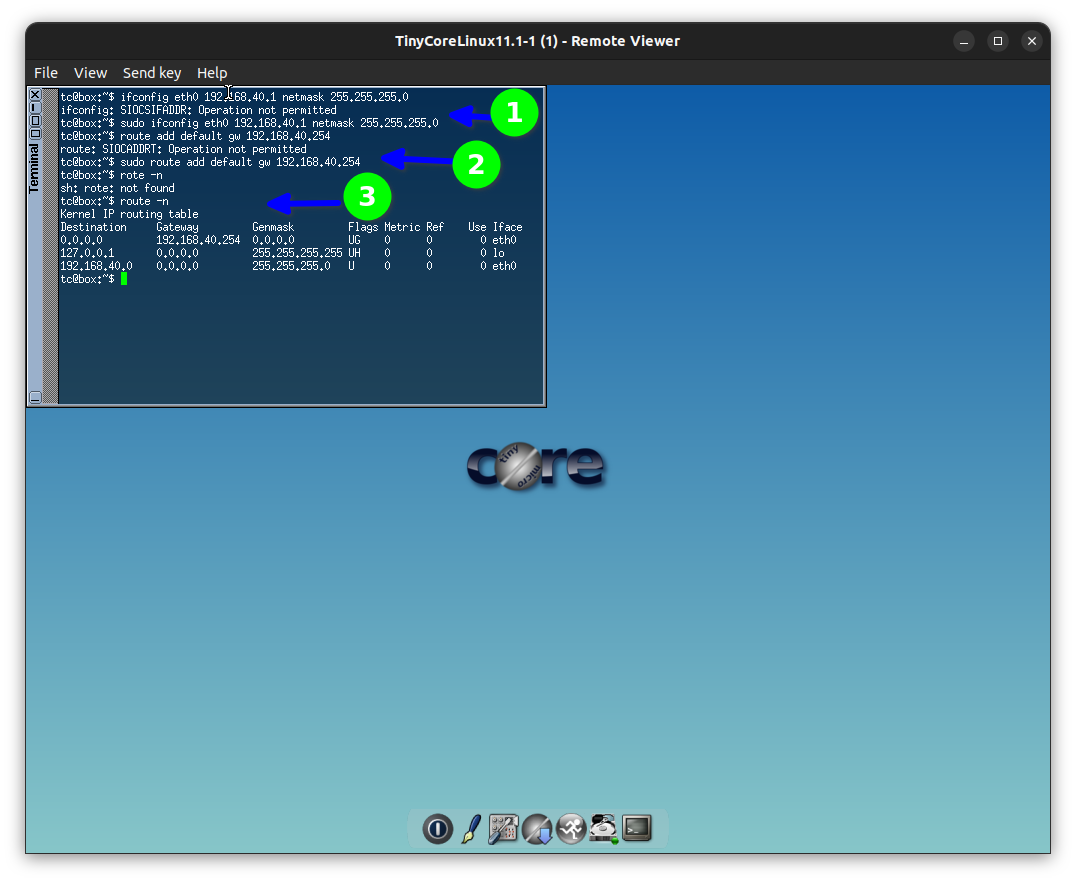
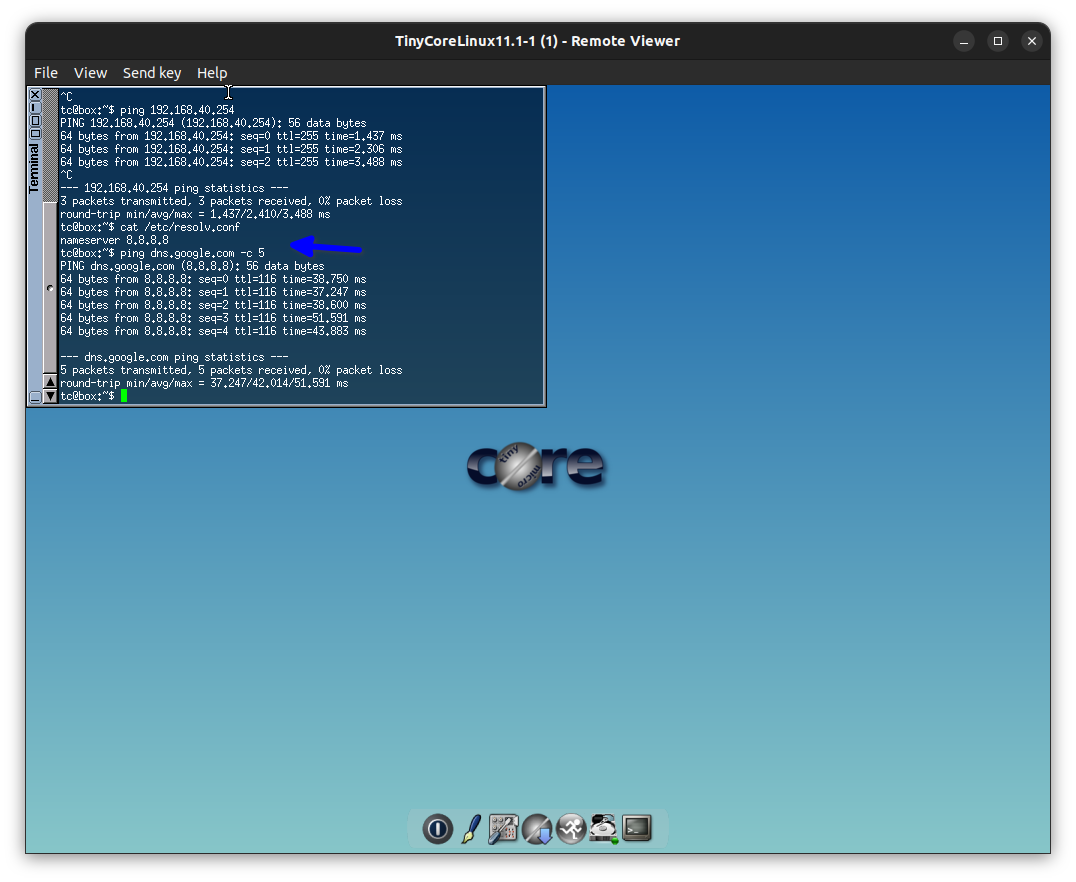
If you like this blog post pls like and share.
Subscribe to my newsletter
Read articles from Elinathan Olotu directly inside your inbox. Subscribe to the newsletter, and don't miss out.
Written by

Elinathan Olotu
Elinathan Olotu
I am a Cloud Engineer with a strong foundation in multi-cloud environments, specializing in AWS and Azure with hands-on experience in Google Cloud Platform (GCP). Skilled in architecting and optimizing secure, scalable cloud infrastructures, I bring a robust background in Cisco networking to enhance connectivity and reliability. Passionate about leveraging cloud technologies to solve complex challenges, streamline operations, and drive innovation.