vRA: Developing a NSX-T Blueprint – Part1

Dave DavisDave Davis
10 min read

In today’s post, we will I’ll be talking about developing an NSX-T blueprint for vRealize Automation. Having developed live lab exams in the past using vCloud Director I figured it would be interesting to do the same thing but with vRealize Automation and NSX-V. I initially started simple creating a 3-node vSAN cluster blueprint to get my feet wet and work out any “gotchas”. After successfully deploying said blueprint I decided to take it further this time deploying a full NSX-T environment. NSX-T has been gaining traction in the enterprise space so it makes sense and would allow our organization to leverage it for training and demonstrations.

Requirements:

  • Multiple deployments with repeatable results

  • Dynamic routing (BGP)

  • Allow for installation of solutions like PCF / PKS

  • Demonstrate NSX-T capabilities

  • 3 tier app deployed and operational

  • Approval policy in place (due to the size of the blueprint)

  • Lease duration

NSX-T Blueprint Design

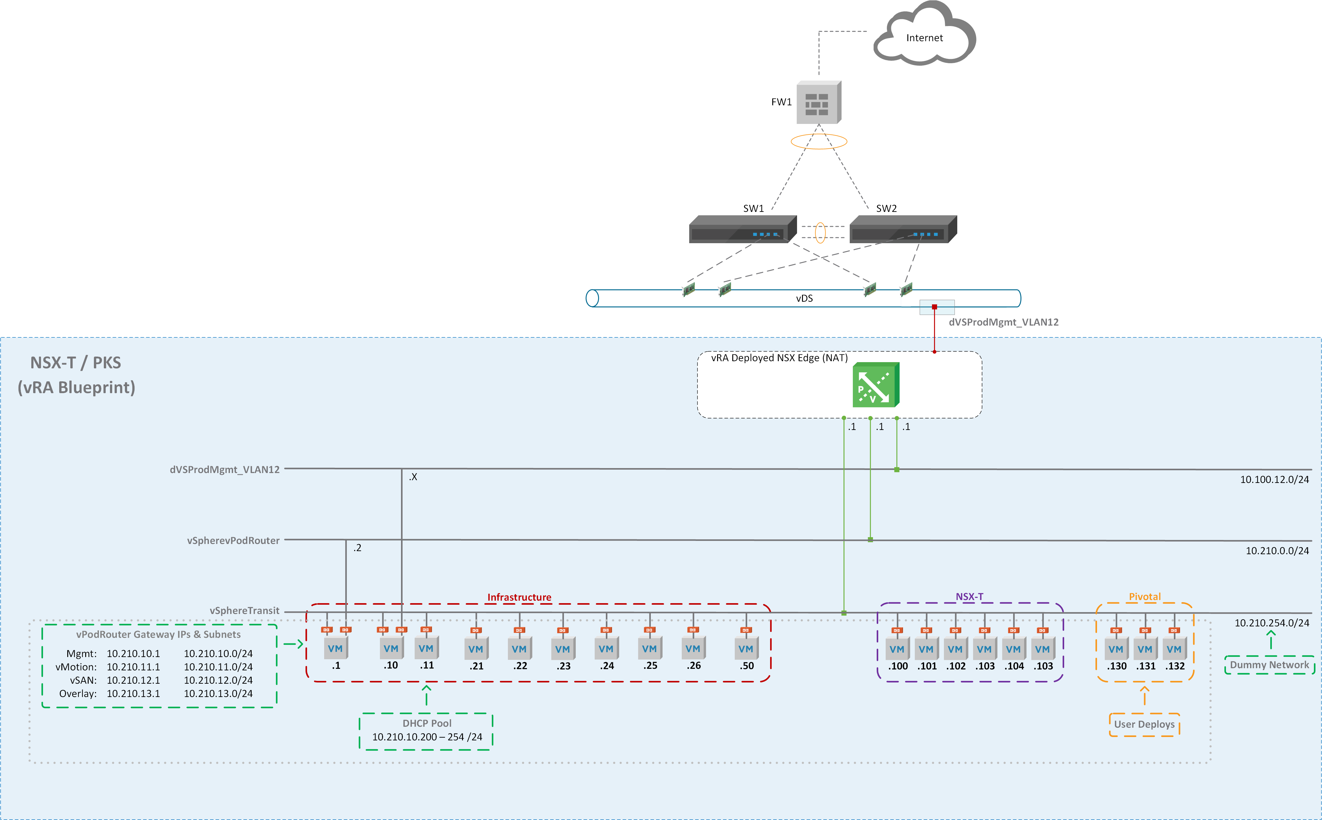
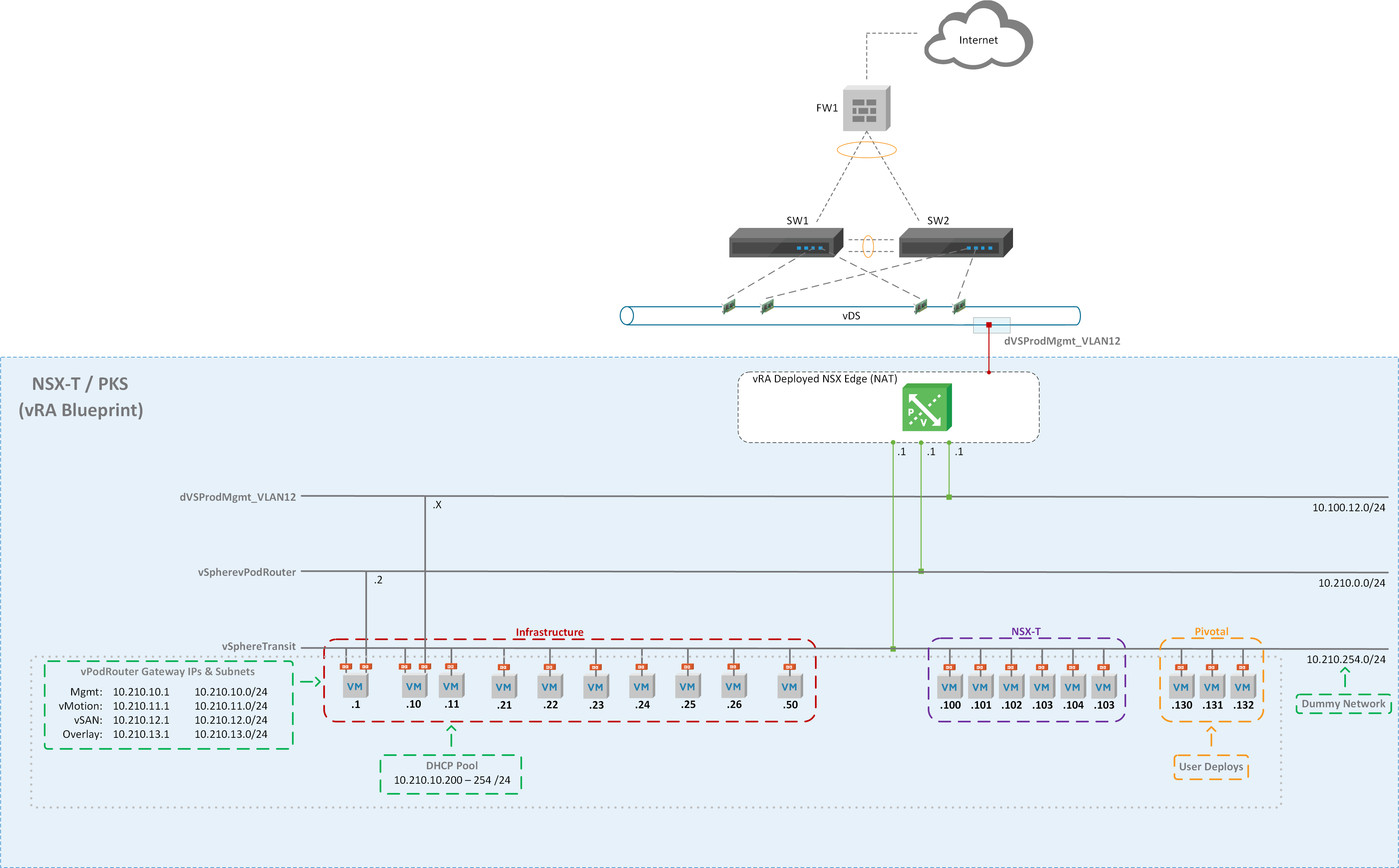
Diagram illustrating a network architecture labeled "NSX-T / PKS (vRA Blueprint)." It includes components like the internet, firewall, switches, and NSX Edge. The network is segmented into different VLANs and subnets, with sections for infrastructure, NSX-T, pivotal, and dummy networks. VMs and router gateways are labeled with specific IP ranges.

Figure1 – NSX-T Diagram

Creating the Dev Environment

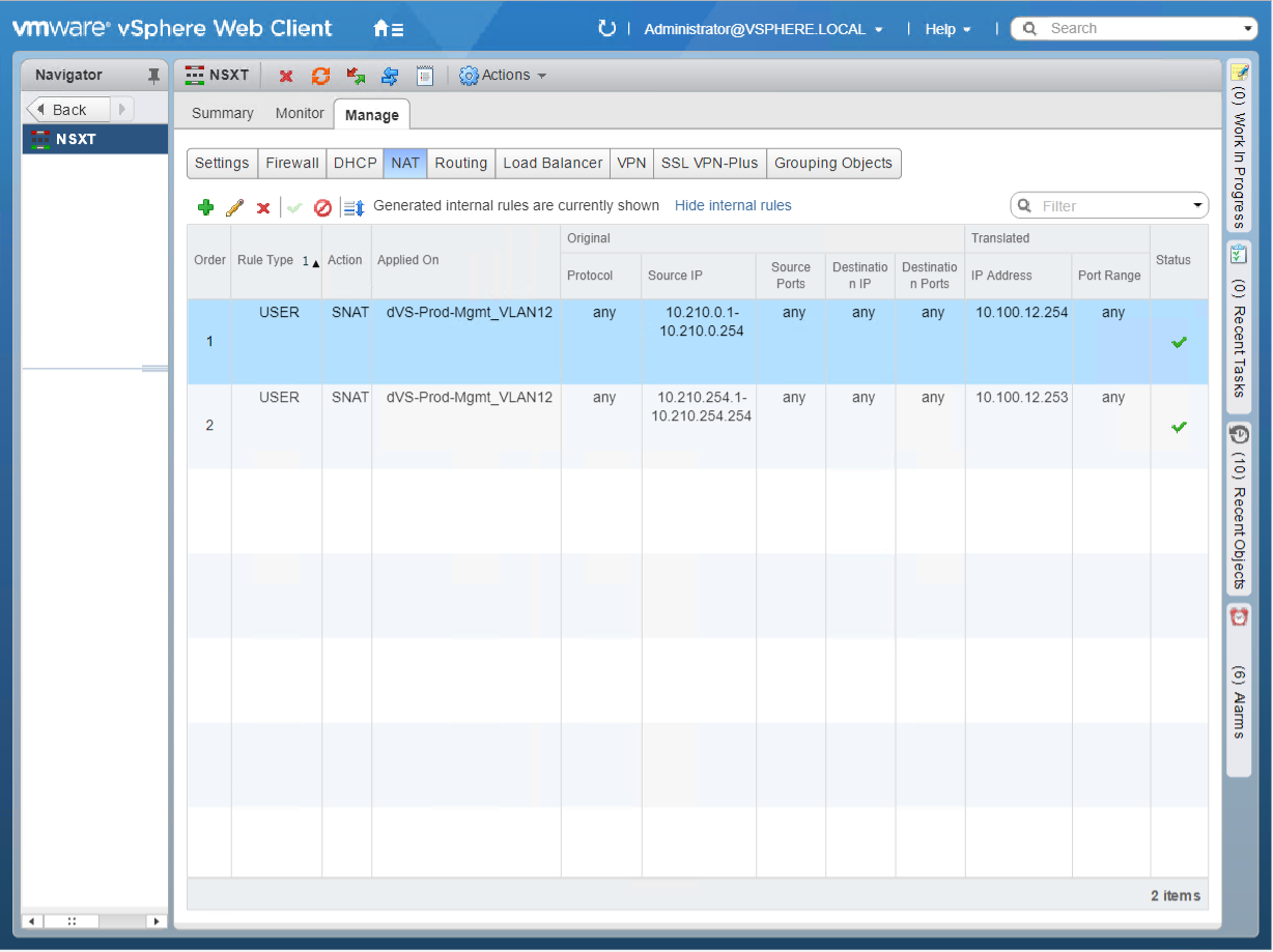
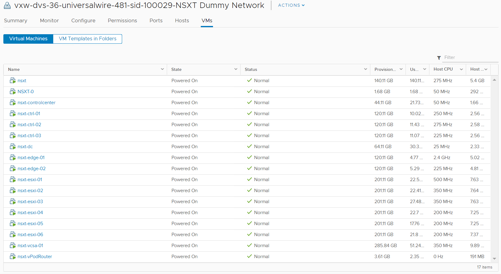
The diagram above (Figure1) shows the end game of the NSX-T blueprint but before we can build the vRA blueprint we need to create a development environment leveraging NSX-V components. I created NSX Edge called “NSXT” that has 3 interfaces connected to their respective port group / logical switches (Figure2) and NAT applied on the uplink interface (Figure3). This allows us to deploy our NSX-T environment in isolation. All virtual machines will be assigned to logical switch “NSXT Dummy Network” as shown in Figure4. The external interface of the vPodRouter will be connected to “NSXT vPodRouter Network” and the ControlCenter external interface will be connected to the vDS port group “dVS-Prod-Mgmt_VLAN12” as illustrated in Figure1. We’ll have 16 total virtual machines that will make up the vRA NSX-T blueprint once everything is said and done.


Important:

  1. Make sure Promiscuous mode, MAC address change, and Forged transmit have been set to “Accept” otherwise our nested virtual machines and the NSX-T Overlay won’t work properly.

  2. Set the MTU size on the vDS that’s hosting the nested environment to 9000. In the dev environment, I couldn’t get jumbo frames (9000) to successfully work when testing with vmkping so I dropped the MTU down to 8000 for the nested vDS and VMkernel interfaces. I believe this has to do with VXLAN overhead but need to capture some packets to confirm.
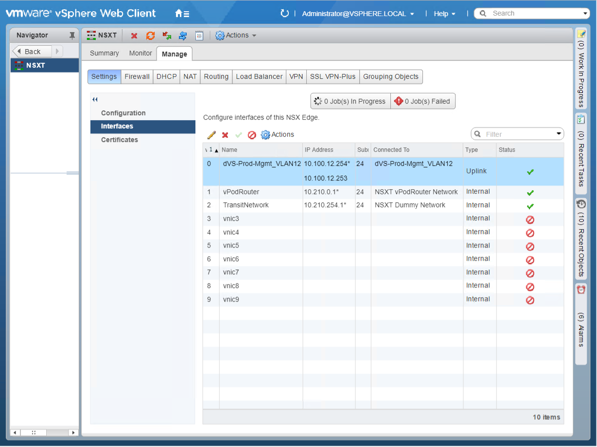
Screenshot of the VMware vSphere Web Client interface showing the configuration of NSX Edge interfaces. Various interfaces are listed with details like name, IP address, and connection status, including both uplinks and internal connections.

Figure2 – NSX Edge Interfaces

Screenshot of the VMware vSphere Web Client showing the NAT configuration page with two SNAT rules listed. Each rule has details such as source IP, destination IP, and translated IP addresses, applied on "dVS-Prod-Mgmt_VLAN12". Status of both rules is active.

Figure3 – NSX Edge NAT

A screenshot of a virtual machine management interface displaying a list of VMs in a network called "NSXT Dummy Network." Each VM shows its name, state (powered on), status (normal), provisioned storage, used storage, host CPU usage, and host memory usage.

Figure4 – NSXT Dummy Network

Virtual Machine Configurations

To keep this post manageable I won’t be providing the step by step details as most folks are familiar with deploy vSphere components and the NSX-T documentation is pretty good too. I will, however, provide screenshots of specific settings made to the NSX-T environment:

DOMAIN CONTROLLER:

  • Update/Patch OS

  • Install the following roles:

    • AD DS

    • DHCP

    • DNS

    • File and Storage Services (NFS)

CONTROLCENTER:

  • Update/Patch OS

  • Customize Windows Profile – This is why we don’t want to use a custom spec in vRA

    • SSH, WinSCP, RDCMan, Chrome, Firefox, and Map a Network Share
  • Additional configurations:

    • vRA Configuration will be discussed in follow up post:

      • Install vRA guest agent

        • Change default route metric [Software Component]

        • Assign static IP Address [Software Component]

        • Bind IP Address to ControlCenter [Bindings]

    • Rename Network Adapters (Figure5)

    • Add persistent route to the network you will be RDPing from. (Figure6)

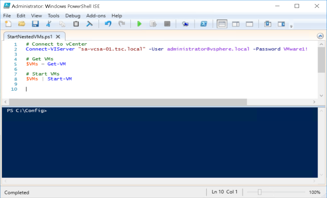
    • Start nested VMs via Task Scheduler during startup (Figure7)
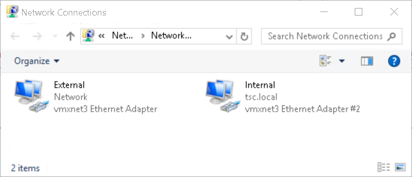
      Screenshot of a Windows Network Connections folder showing two network connections: "External" with vmxnet3 Ethernet Adapter and "Internal" with vmxnet3 Ethernet Adapter #2.

      Figure5 – Rename Network Adapters

      A Windows PowerShell window displaying a command output of persistent routes. There are two routes listed with their network addresses, netmasks, gateway addresses, and metrics.

      Figure6 – Add Persistent Route

      Screenshot of Windows PowerShell ISE with a script to connect to a vCenter server and start virtual machines. The script includes lines for connecting to the server, retrieving VMs, and starting them.

      Figure7 – Start Nested VMs

  • Applications Installed:

    • mtputty

    • RDCMan

    • WinSCP

    • Chrome / Firefox

      • Bookmarks

VCENTER (Nested):

  • HA Advanced Settings:

    • das.ignoreRedundantNetWarning: true

    • das.isolationaddress: 10.210.10.11 (DC)

    • das.usedefaultisolationaddress: false

  • Alarm Definitions Disabled:

    • vSAN Build Recommendation Engine build recommendation

    • vSAN Performance service status

    • Registration/unregistration of third-party IO filter storage providers fails on a host

  • vSAN Settings Silenced for both Clusters (RVC):

    • SCSI controller is VMware certified

NSX-T:

  • IP Pools:

    • ESXi-Pool:

      • IP Range: 10.210.13.21 – 10.210.13.26

      • Gateway: 10.210.13.1

    • CIDR: 10.210.13.0/24

    • DNS Servers: 10.210.10.11

    • * DNS Suffix: tsc.local

    • Edge-Pool:

      • IP Range: 10.210.13.27 – 10.210.13.28

      • Gateway: 10.210.13.1

      • CIDR: 10.210.13.0/24

      • DNS Servers: 10.210.10.11

      • DNS Suffix: tsc.local

  • Fabric

    • Transport Zones

      • TZ-Overlay

      • TZ-VLAN

    • Nodes

      • Hosts:

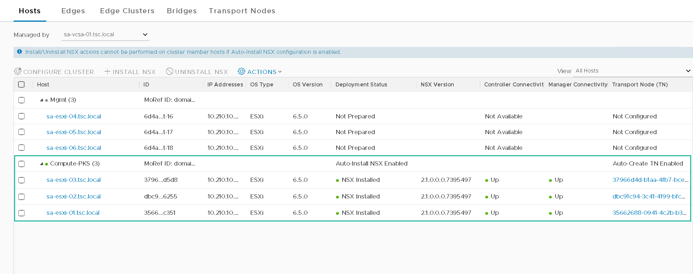
        • Prep only the Compute-PKS Cluster (Figure8)
      • Edges:

        • nsxt-edge-01

        • nsxt-edge-02 (Not added to edge cluster)

      • Transport Nodes:

        • sa-esxi-01

        • sa-esxi-02

        • sa-esxi-03

        • nsxt-edge-01

  • Routing:

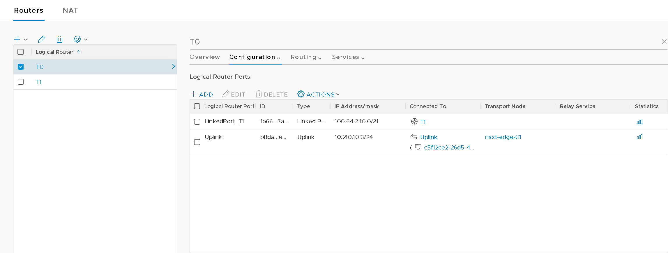
    • Tier0 (Figure9)

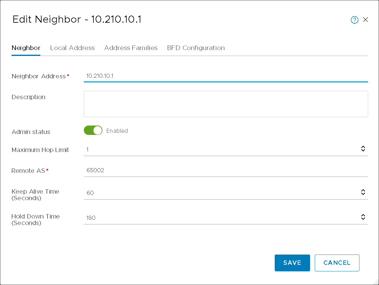
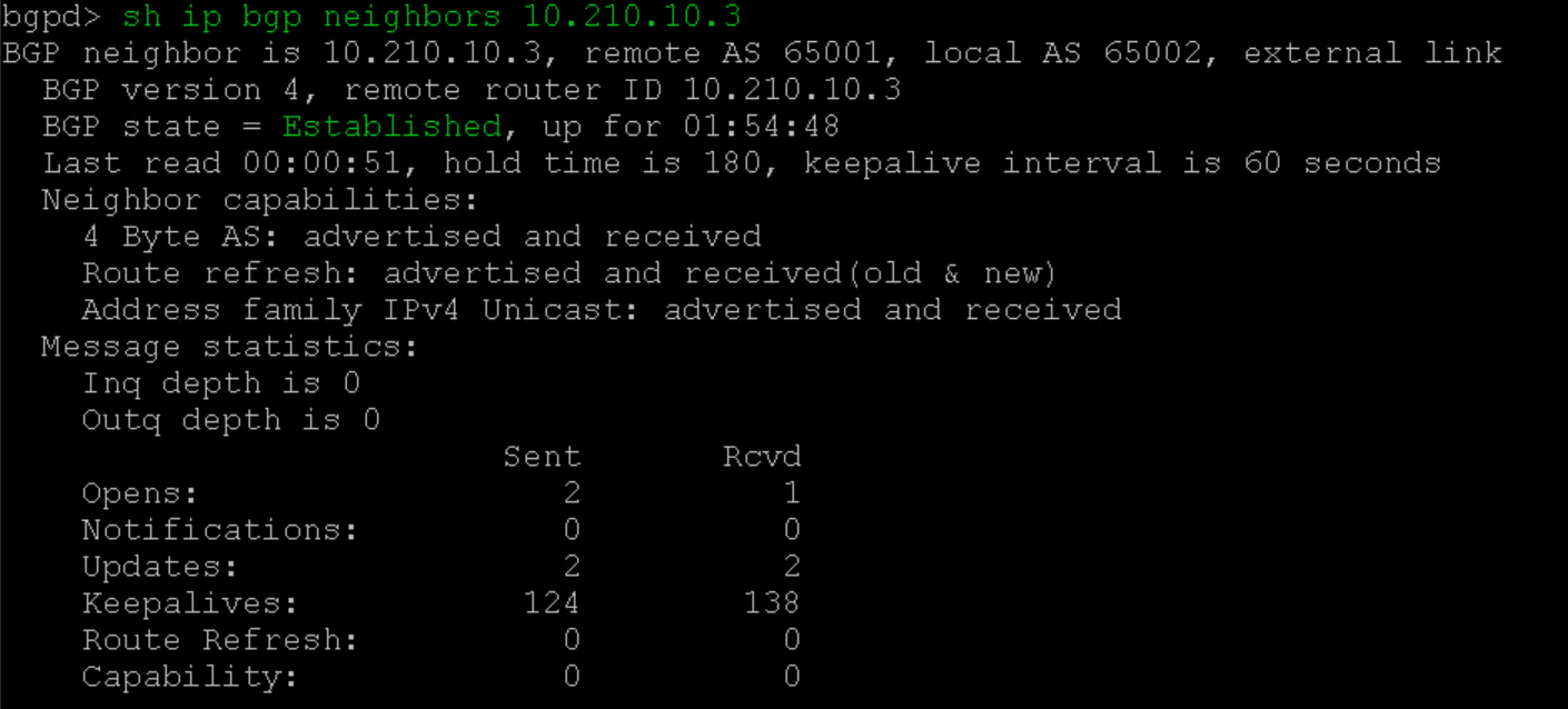
      • T0 BGP neighbor with vPodRouter (Figure10a)

      • vPodRouter BGP neighbor with T0 (Figure10b)

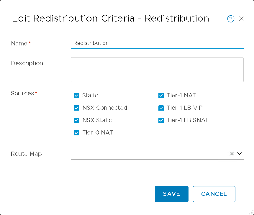
      • Redistribute Routes: All Sources (Figure11)

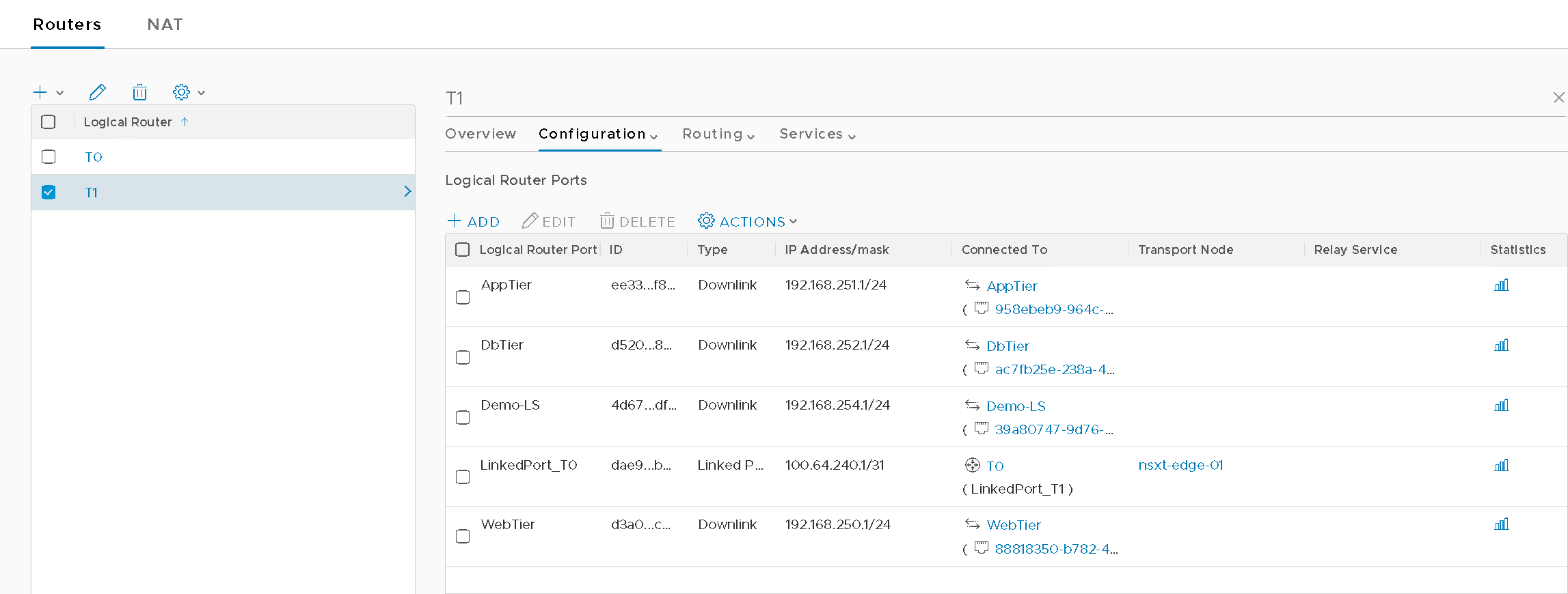
    • Tier1 (Figure12)

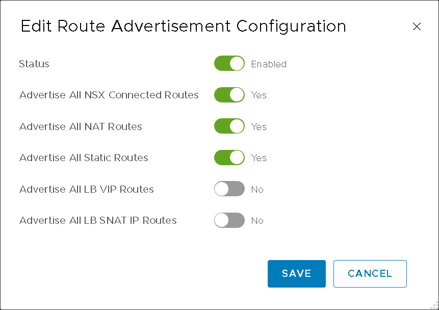
      • Route Advertisement (Figure13)
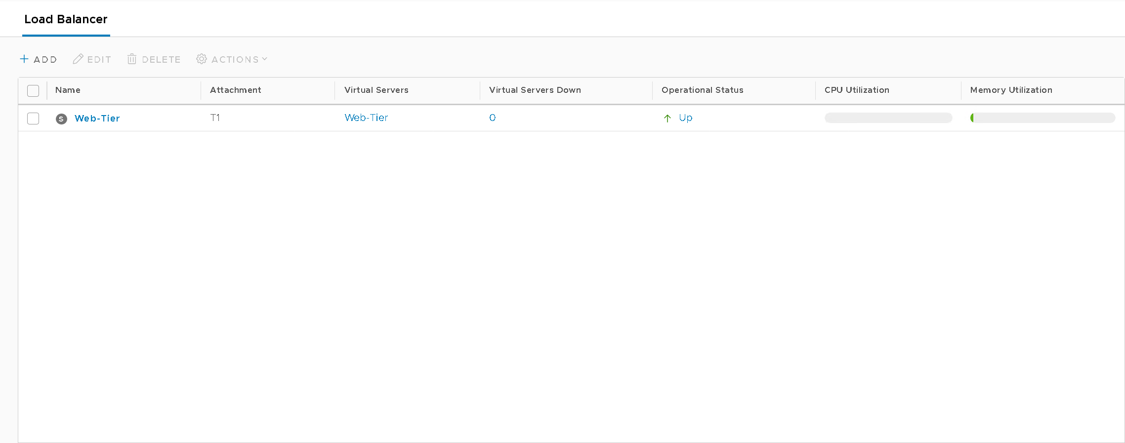
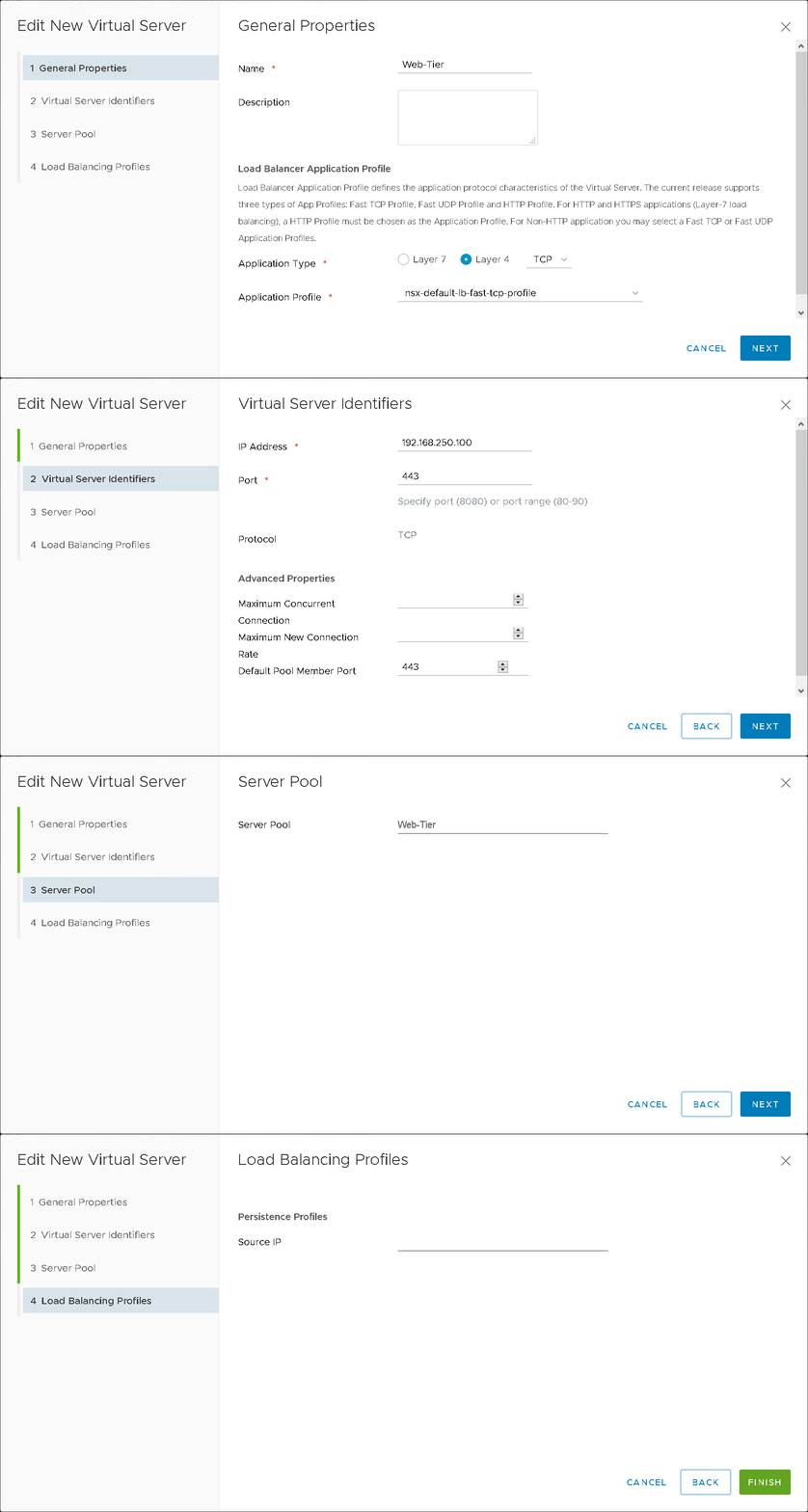
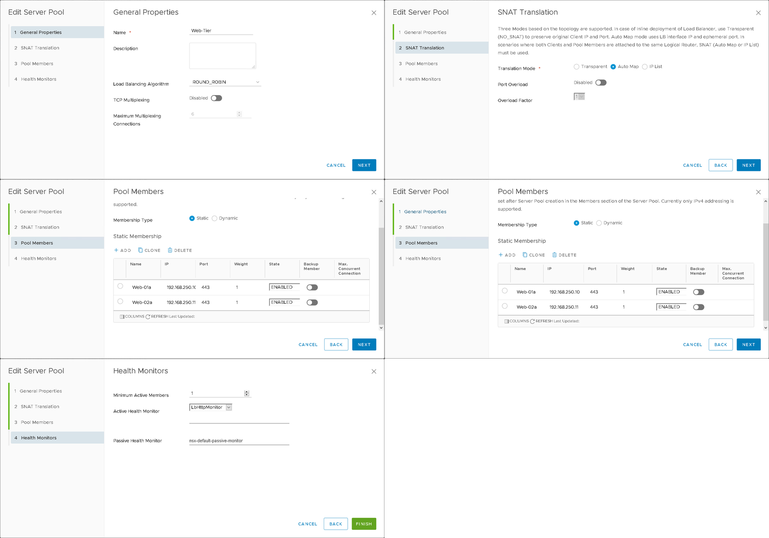
  • Load Balancing:

    • Load Balancers (Figure14)

    • Virtual Servers (Figure15)

    • Server Pools (Figure16)

A screenshot of a software interface displaying a list of hosts under "Mgmt" and "Compute-PKS" categories. Hostnames, IP addresses, OS types, OS versions, deployment statuses, NSX versions, and connectivity statuses are shown. Some entries indicate "NSX Installed" with a status of "Up."

Figure8 – Compute-PKS Cluster

Screenshot of a configuration page for logical routers, showing two entries: "LinkedPort_T1" with IP address 100.64.240.0/31 connected to T1, and "Uplink" with IP address 10.210.10.3/24 connected to nsxt-edge-01. Options to add, edit, or delete are visible at the top.

Figure9 – T0 Configuration

Editing interface for a network neighbor configuration. Fields include Neighbor Address, Description, Admin Status (enabled), Maximum Hop Limit, Remote AS, Keep Alive Time, and Hold Down Time, with options to Save or Cancel.

Figure10a – T0 BGP Configuration

A terminal screen displaying BGP neighbor information. The neighbor at IP address 10.210.10.3 is established, with message statistics showing keepalives sent and received. Various neighbor capabilities and session details are listed.

Figure10b – vPodRouter neighbor

A settings window titled "Edit Redistribution Criteria - Redistribution" with fields for Name, Description, Sources, and Route Map. The Name is set to "Redistribution." Checkboxes for various sources are selected, including Static, NSX Connected, NSX Static, Tier-0 NAT, Tier-1 NAT, Tier-1 LB VIP, and Tier-1 LB SNAT. There are "Save" and "Cancel" buttons at the bottom.

Figure11 – T0 Redistribution

A screenshot of a network interface showing the configuration of logical router ports for "T1". The ports listed include AppTier, DbTier, Demo-LS, LinkedPort_TO, and WebTier, with associated IDs, types (mostly Downlink), IP addresses/masks, and connected components. Options for adding, editing, or deleting are available.

Figure12 – T1 Configuration

Settings interface for "Edit Route Advertisement Configuration" with toggles for enabling route advertising. Options for NSX Connected, NAT, and Static Routes are enabled, while LB VIP and SNAT IP Routes are disabled. Save and Cancel buttons are at the bottom.

Figure13 – T1 Route Advertisement

Screenshot of a Load Balancer dashboard showing a service named "Web-Tier." It displays details like attachment "T1," no virtual servers down, operational status "Up," and CPU and memory utilization bars.

Figure14 – NSX-T WebTier LB

Screenshot of a "New Virtual Server" setup window, showing "General Properties" for configuring load balancer application profile settings. Options include application type selection (Layer 7 or Layer 4) and a dropdown for choosing the application profile. The "NEXT" button is at the bottom right.

Figure15 – NSXT LB Virtual Server

This image shows a "Edit Server Pool" interface with options for General Properties. The form includes fields for Name, Load Balancing Algorithm set to "ROUND_ROBIN," and TCP Multiplexing, which is disabled. There is also a "Maximum Multiplexing Connections" field set to 6. Navigation options include Cancel and Next buttons.

Figure16 – NSXT LB Server Pool

Once you have gone through the configuration process for all your virtual machines it should look similar to Figure17.
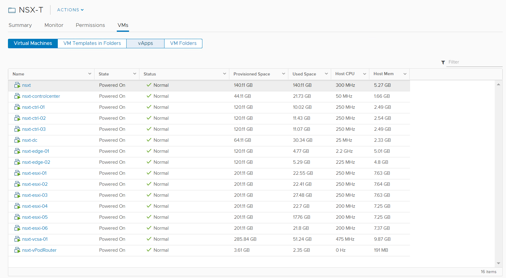
A screenshot of the NSX-T dashboard displaying a list of virtual machines. It shows details such as name, state, status, provisioned space, used space, host CPU, and host memory for each virtual machine. All machines are powered on and have a status of "Normal."

Figure17 – Results

THE NESTED ENVIRONMENT

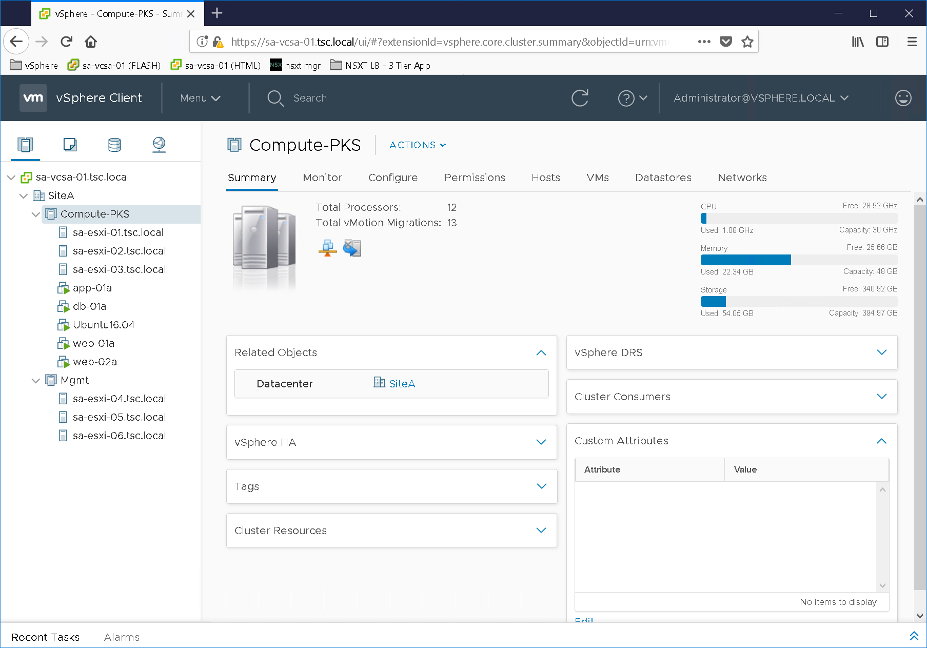
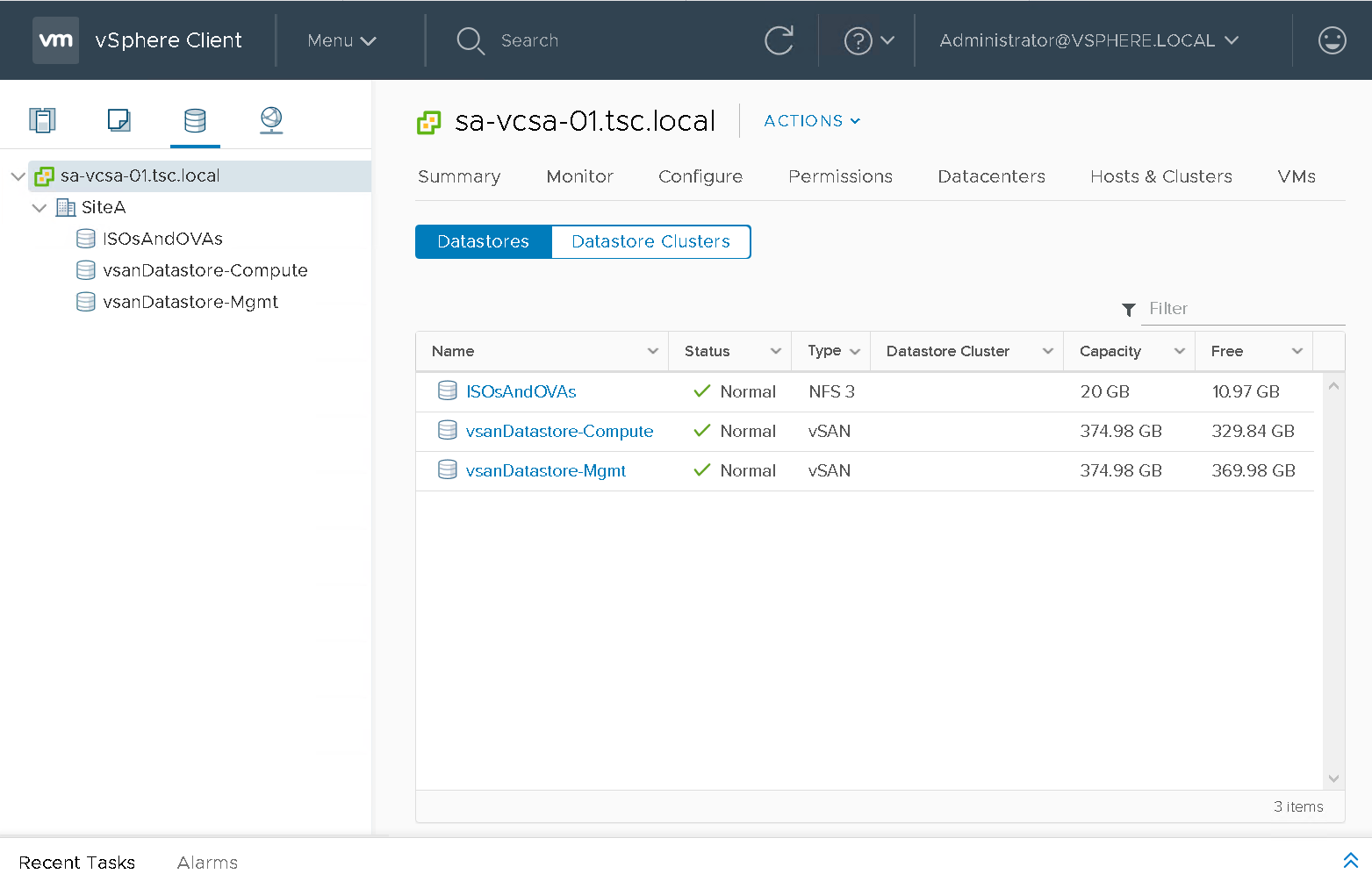
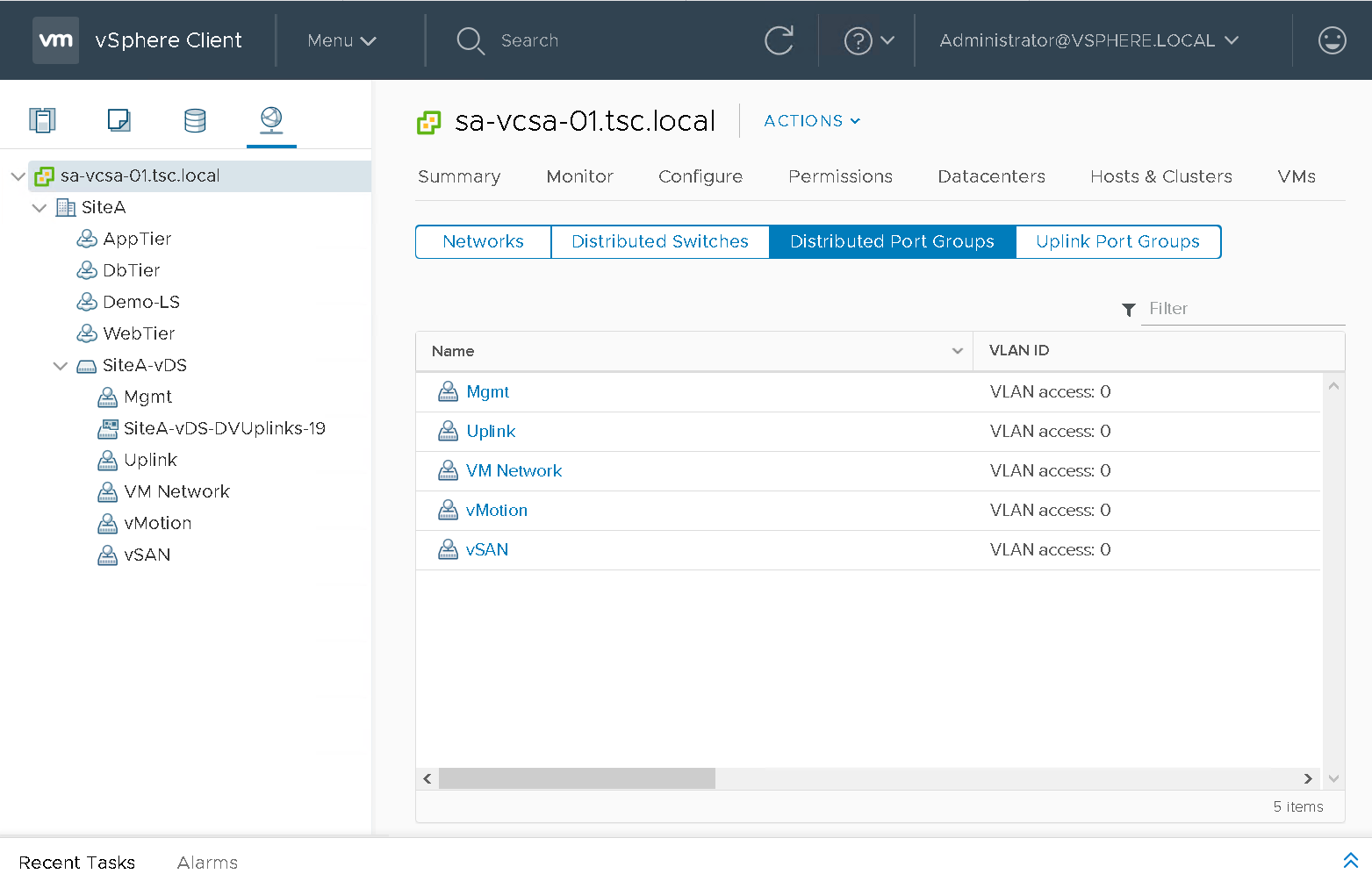
Below are a couple screenshots of the NSX-T Dashboard (Figure18) and vCenter (Figure19). This environment should allow individuals the ability to deploy PKS with the management components deployed to the Mgmt cluster and the K8s clusters to the Compute-PKS cluster.
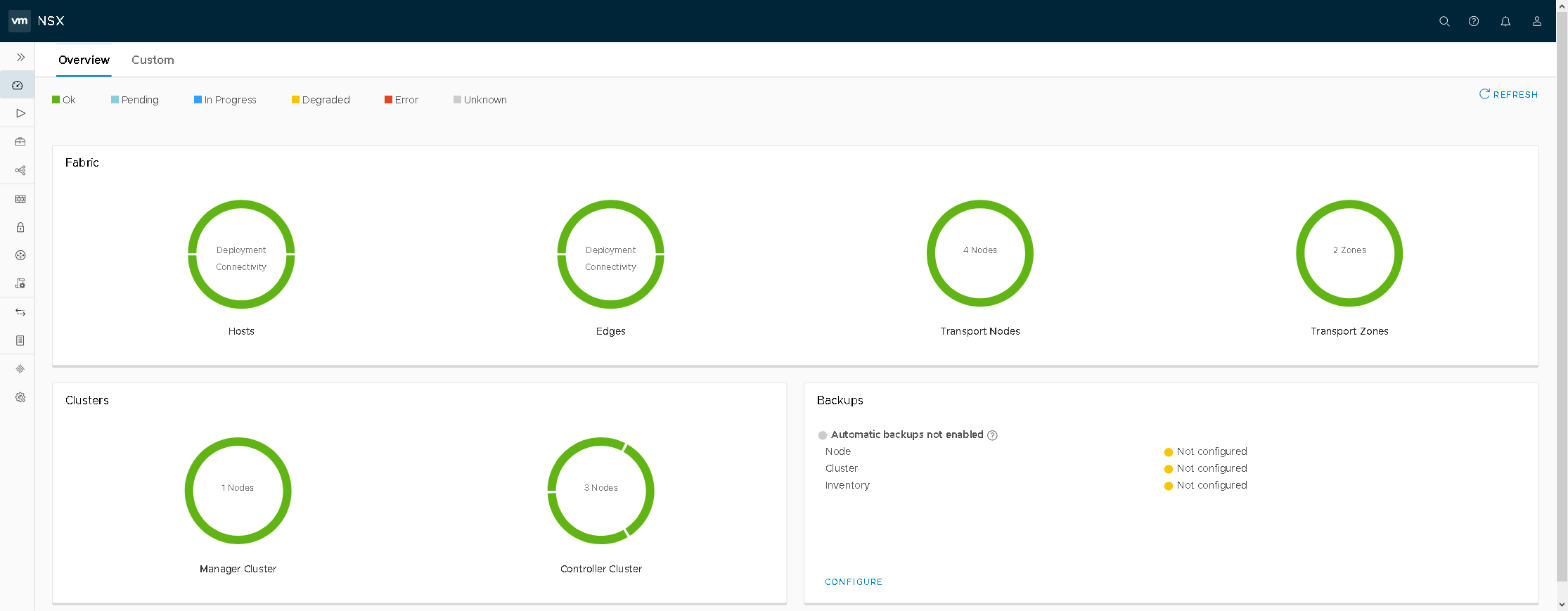
Dashboard of the NSX interface showing the status of Fabric and Clusters with green circles indicating deployment and connectivity. It also shows backup status as "Automatic backups not enabled" with related configurations not set up.

Figure18 – NSX-T Dashboard

Screenshot of the vSphere Client interface showing the summary tab for "Compute-PKS" under "SiteA". It displays total processors (12), vMotion migrations (13), and resource usage for CPU, memory, and storage. The left pane lists network items, and the right pane includes related objects, and sections for vSphere DRS, HA, tags, cluster resources, and custom attributes.

Figure19 – vCenter Hosts / Clusters

Screenshot of the vSphere Client showing datastores on a server. It lists three datastores: ISOsAndOVAs, vsanDatastore-Compute, and vsanDatastore-Mgmt with statuses marked as Normal. Types include NFS 3 and vSAN. Each datastore's capacity and free space are displayed.

Figure20 – vCenter Datastores

Screenshot of a vSphere Client interface displaying a network configuration. The left panel shows a hierarchy of networks under "SiteA," and the right panel lists distributed port groups with names like "Mgmt," "Uplink," and "VM Network," each having VLAN access set to 0.

Figure21 – vCenter Networks

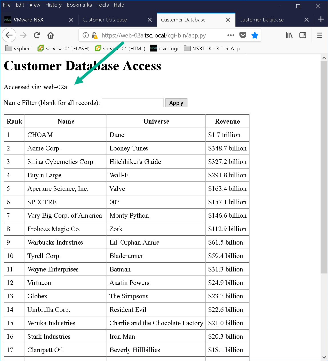
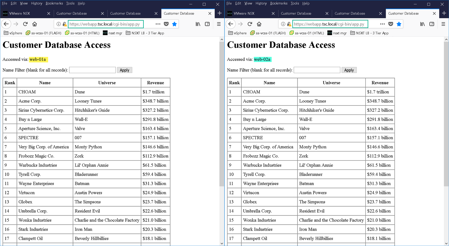
As you can see from Figure19 we have a basic 3 tier application deployed in order to test NSX-T load balancer. The 3 tier application was created using Doug Baer’s three-part series called “HOL Three-Tier Application“. Thank you, Doug, for the excellent post! Once the VMs were deployed I attached them to their respective logical switches. I confirmed both web tier VMs (Figure22 & Figure23) were accessible as well as the NSX-T LB VIP “webapp.tsc.local” (Figure24):
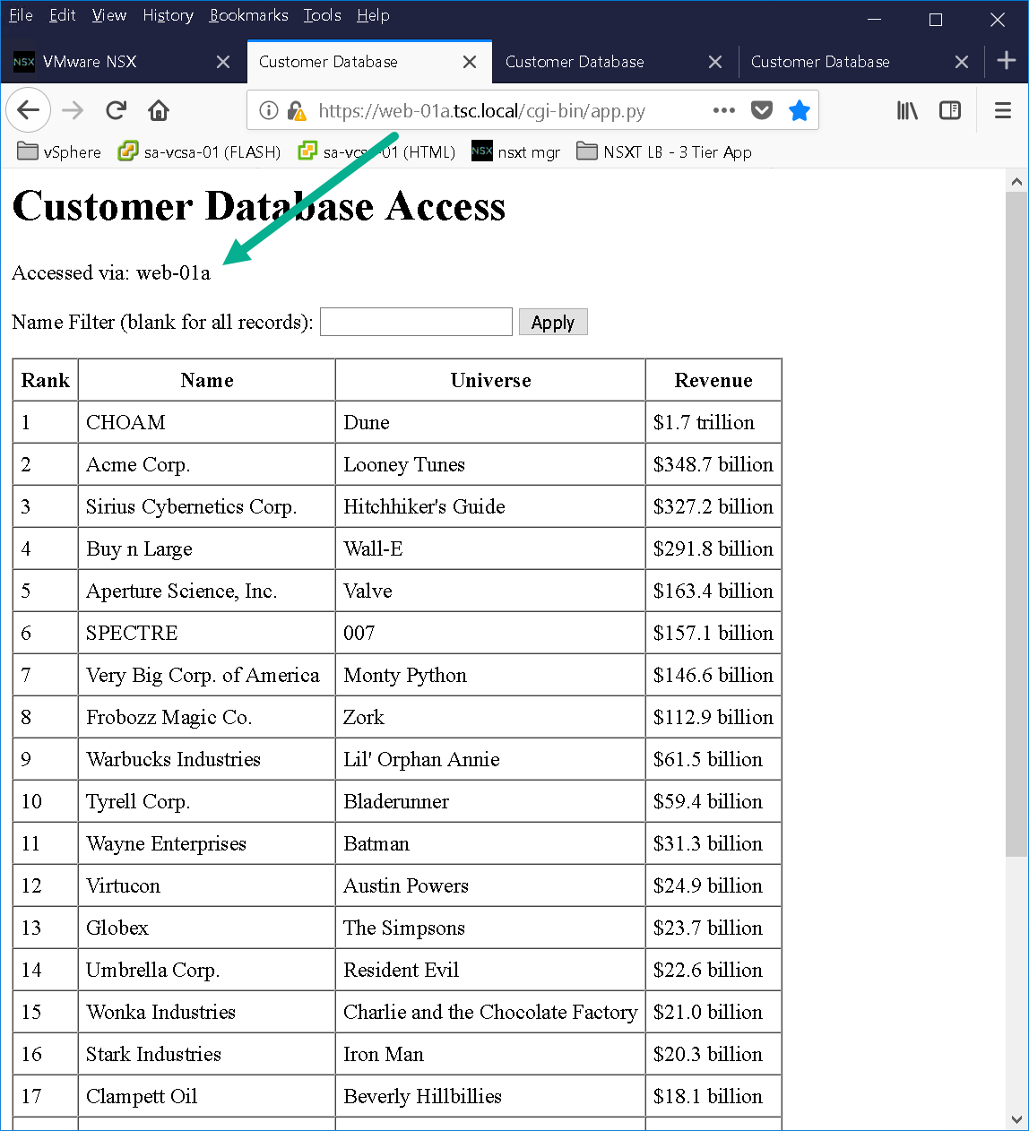
A browser window displaying a fictional customer database with a list of companies from various universes. The table shows their rank, name, universe, and revenue. The page header indicates access via "web-01a".

Figure22 – Web-01a

Screenshot of a "Customer Database Access" webpage displaying a table with fictional companies, their associated universes, and revenues. The webpage is accessed via "web-02a". The table shows rankings of companies like CHOAM from "Dune" with $1.7 trillion and Acme Corp. from "Looney Tunes" with $348.7 billion, among others.

Figure23 – Web-02a

A browser window displays a "Customer Database Access" page. It lists fictional companies ranked by revenue, including CHOAM from the "Dune" universe with $1.7 trillion and Acme Corp. from "Looney Tunes" with $348.7 billion. The database is accessed via "web-01a". A search filter is available.

Figure24 – WebApp VIP

CONVERT TO TEMPLATES

Create a temp vDS port group to put your virtual machines on before converting to templates. When I deployed the blueprint I realized some of my ESXi hosts were still attached to the original dev logical switch as shown in Figure25.
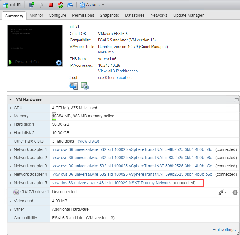
Screenshot of a virtual machine summary in VMware showing details like the guest OS version (VMware ESXi 6.5), compatibility, hardware specifications (CPU, memory, hard disks), and connected networks. One network adapter is highlighted, indicating connection to a "NSX-T Dummy Network."

Figuer25 – Network Adapter 5 still attached to Dev LS

With testing complete and all virtual machine network adapters on a temp port group its now time to shut down the NSX-T dev environment and convert the virtual machines to templates save your wrist and use PowerCLI to accomplish this! That’s going to wrap up this post stay tuned for the next post, where we will go through the process of creating our NSX-T vRA Blueprint!

0
Subscribe to my newsletter

Read articles from Dave Davis directly inside your inbox. Subscribe to the newsletter, and don't miss out.

Written by

Dave Davis
Dave Davis