vRA: Developing a NSX-T Blueprint – Part2
 Dave Davis
In the previous post, I discussed how to setup a development environment, configuration settings made to the virtual machines and converting virtual machines to templates. This post assumes vRA is operational as I’ll be discussing the following topics as it relates to creating/publishing the NSX-T Blueprint that will be used to deploy PKS.
Network Profiles & Reservation
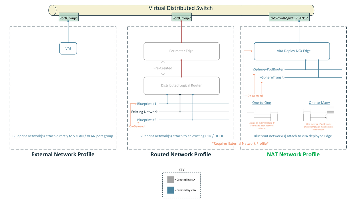
Network profiles contain pre-defined IP information like gateway, subnet, DNS, and IP address ranges. When a virtual machine is provisioned vRA will assign an IP address based on the information in the network profile. There are three types of Network Profiles as depicted in Figure1. I have opted for NAT network profile (One-to-Many) in order to support multiple deployments. In Figure2 are the network profiles I created for the blueprint. Next, we have to tie the external network profile with our existing port group as shown in Figure3.
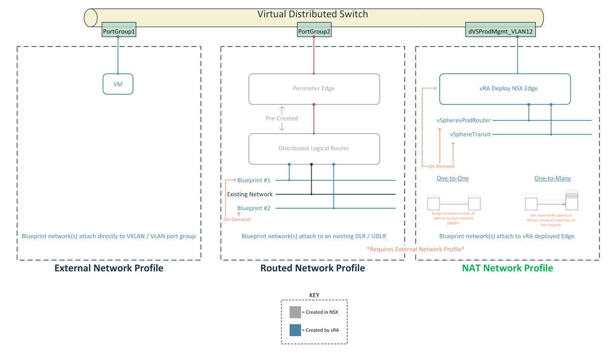
Figure1 – vRA Network Profiles
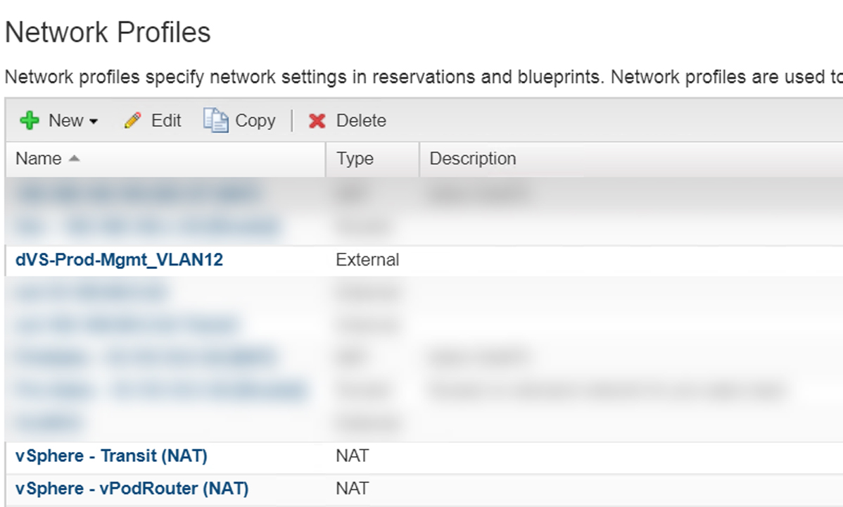
Figure2 – Network Profiles
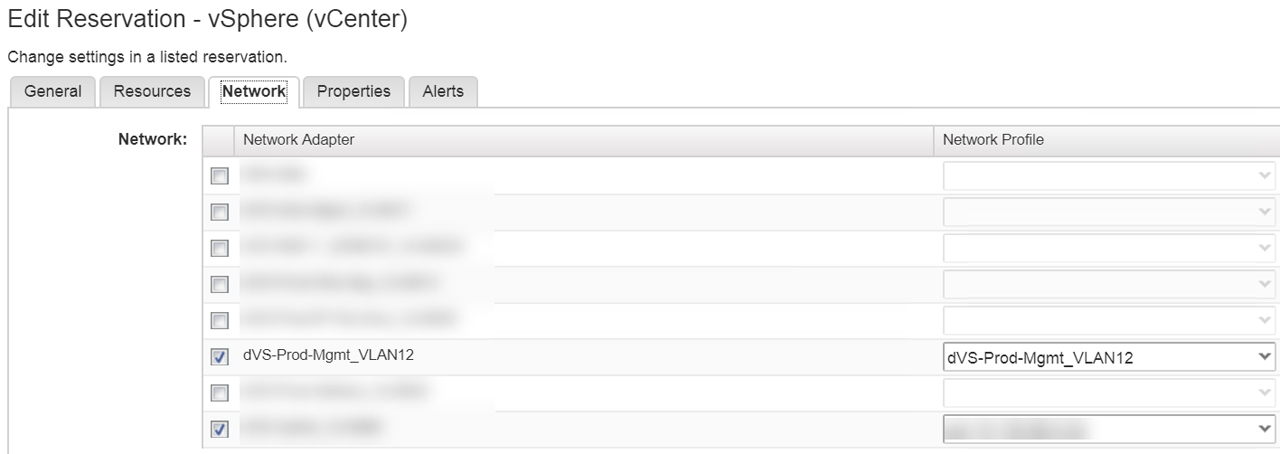
Figure3 – Apply Network Profile to Network Adapter
Software Component
Custom specification will destroy any user profile (tsc\administrator) custom configurations we make like MTputty, WinSCP, Chrome/Firefox bookmarks, desktop image, etc. So in order to access the ControlCenter, we need a way to assign the IP address of the external interface.
During a Livefire training event for Hybrid Cloud in Boston a couple weeks ago I struck up a conversation with classmate Chris Smith who focuses on the Cloud Automation. I explained the situation above to him and wanted to get his perspective. He mentioned the easiest way is to use Software Components with bindings. After the completing our session for the day I went back to the hotel and began playing with Software Components/bindings and to my surprise, it just worked! So a huge thank you to Chris for sharing the knowledge. Please check out his site here as he has excellent content around vRA.
SetExternalIP
The first software component I created was SetExternalIP and created a property called “cc_ip”. We will use this property later when we configure binding. Then proceeded to Actions where I created a basic script that sets the IP address of the External interface. I take the IP address based on the cc_ip property and assign it to [string]$IP. Line 1 of the code below ensure the variable is a string then passes it to the -IPAddress property of New-NetIPAddress cmdlet. The -InterfaceAlias property references the network adapter “External” that was changed in the previous post.

Figure4 – SetExternalIP Software Component: Properties
[string]$ip = $cc_ip
New-NetIPAddress –InterfaceAlias “External” -IPAddress $ip `
                 –PrefixLength 24 -DefaultGateway 10.100.12.x `
                 -AddressFamily IPv4 -Confirm:$false

Figure5 – SetExternalIP Software Component: Action
SetStaticRoute
The SetStaticRoute software component is simpler only having an action that references the External interface again. I increased the metric to ensure traffic goes through the internal interface. During the Blueprint Design phase, we will attach both software components to the nsxt-controlcenter machine.
Set-NetIPInterface -InterfaceAlias External -InterfaceMetric 2000

Figure6 – SetStaticRoute Software Component: Action
Blueprint Design
With the networking and software component portion complete we can now start working on the blueprint design. To ensure our vSphere templates are imported into vRA lets perform an inventory sync as shown in Figure7. Now click on “Design” tab > Blueprints > New give the blueprint a name shown in Figure8. Select the transport zone and reservation policy Figure9.
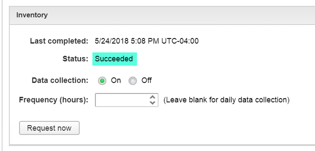
Figure7 – Sync Inventory
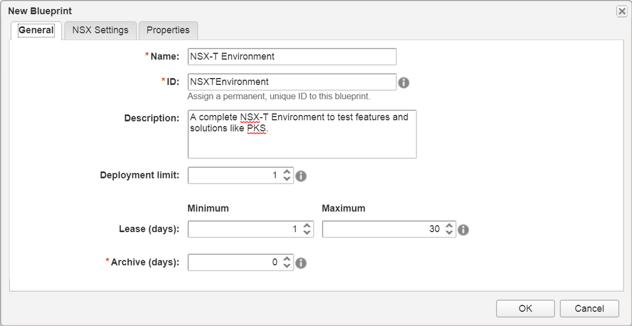
Figure8 – New Blueprint

Figure9 – Select Transport Zone and Reservation
We’ll start with a blank canvas shown in Figure10.

Figure10 – Blank canvas
The first thing to do is drag some network constructs to the canvas Figure11:
1 x Existing Network
2 x On-Demand NAT Network

Figure11 – Add Networks
Next up is the virtual machines we will focus on the vPodRouter and the ControlCenter VMs (Figure12 – Figure16) as all other VMs will be attached to the vSphereTransitNAT network. We drag over a vSphere (vCenter) Machine then configure the machine to use the vPodRouter template we created in the previous post and attach it to the required networks. We have two virtual machines attached to their corresponding networks (Figure17). Now to attach the software components we created earlier to nsxt-controlcenter machine (Figure18) and then bind property “cc_ip” to “_resource~nsxt-controlcenter~ip_address” (Figure19). This will pass the IP address from the nsxt-controlcenter
vPodRouter

Figure12 – Create a vSphere (vCenter) Machine

Figure13 – Assign vSphere template nsxt-vPodRouter

Figure14 – Assign Networks to vPodRouter
ControlCenter

Figure15 – Assign vSphere template nsxt-ControlCenter

Figure 16 – Assign Networks to ControlCenter

Figure17 – Design canvas with 3 networks and 2 virtual machines

Figure18 – Attach SetExternalIP and SetStaticRoute to nsxt-controlcenter machine

Figure19 – Software Component Binding
Rinse and Repeat
Simply repeat the process for the remaining virtual machines that make up the NSX-T blueprint. Your design canvas should look similar to Figure20 once finished.

Figure20 – Design Canvas with all required networks, virtual machines and software components
Below is a breakdown of the dependency order for the virtual machines inside the blueprint:
nsxt-vPodRouter
nsxt-dc
nsxt-esxi-01
nsxt-esxi-02
nsxt-esxi-03
nsxt-esxi-04
nsxt-esxi-05
nsxt-esxi-06
nsxt-vcsa-01
nsxt
nsxt-ctrl-01
nsxt-ctrl-02
nsxt-ctrl-03
nsxt-edge-01
nsxt-edge-02
nsxt-controlcenter
SetExternalIP
SetStaticRoute
vRO PowerShell Host / Event Subscription
Since this is a nested environment we will need to enable the following security policies; Promiscuous Mode, Forged Transits, and MAC Address Changes in order for the virtual machines to communicate. To accomplish we will leverage Event Subscription to initiate a PowerCLI script via a Powershell host in VRO due to my lack of javascript experience but is something I’m working on it ;).
Add PowerShell Host
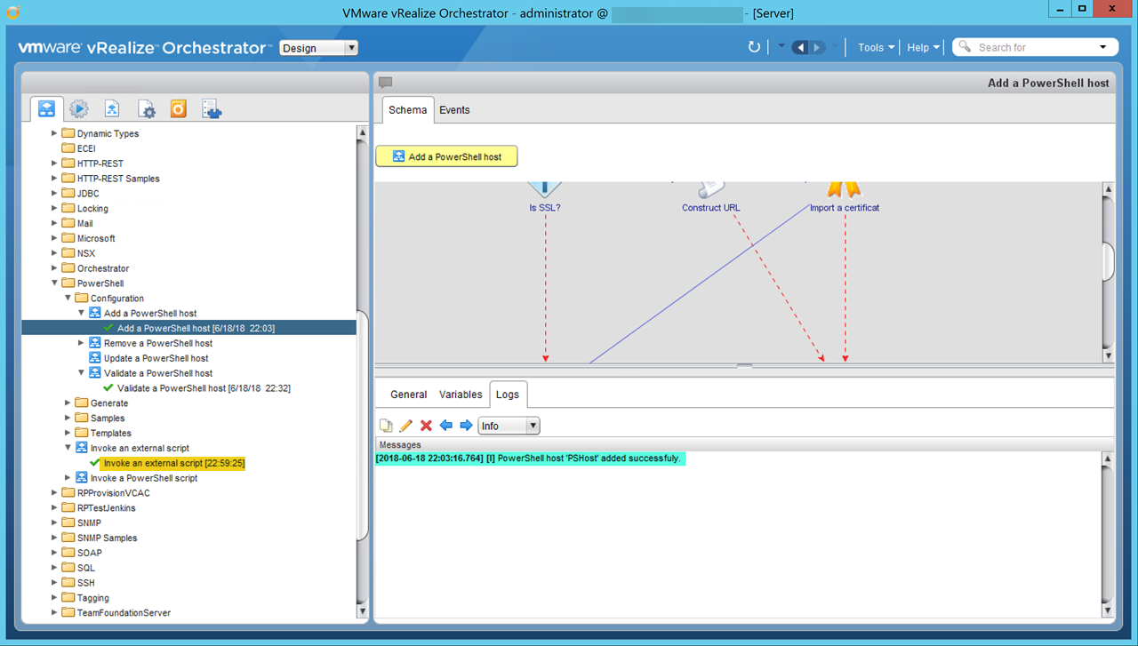
Invoke an External Script
In our case, it’s just a simple .ps1 file withWrite-Output “Testing ;)”to validate things work. You can see in the screenshot above Invoke an external script ran successfully.
Important: In order to get the scripts to execute successfully I had to update the PowerShell plugin from 1.0.11 to 1.0.13 after doing so the scripts ran without issue.
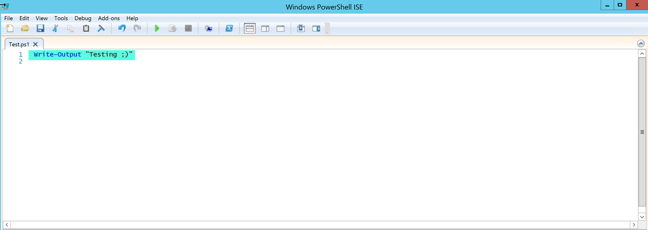
Figure22 – Simple script to test functionality
* Create a vRO workflow that will process the vRA payload looking for the two on-demand networks by finding the port group ids then passing that information to the PowerCLI script that will enable Promiscuous Mode, Forged Transits, and MAC Address Change.
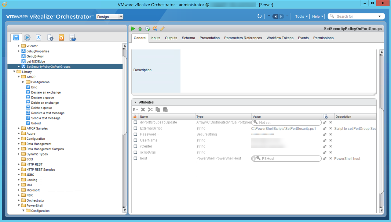
Figure23 – SetSecurityPolicyOnPortGroups Workflow – Attributes
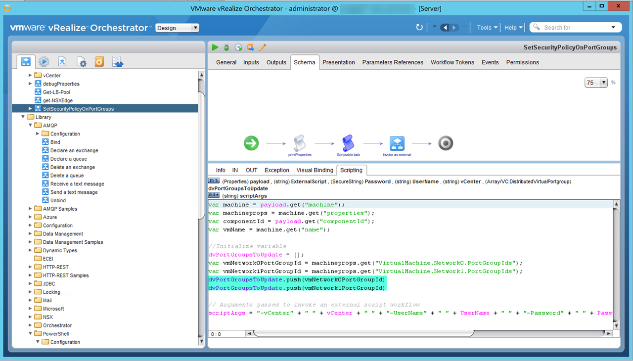
Figure24 – SetSecurityPolicyOnPortGroups Workflow – Script to extract port group ids created by vRA
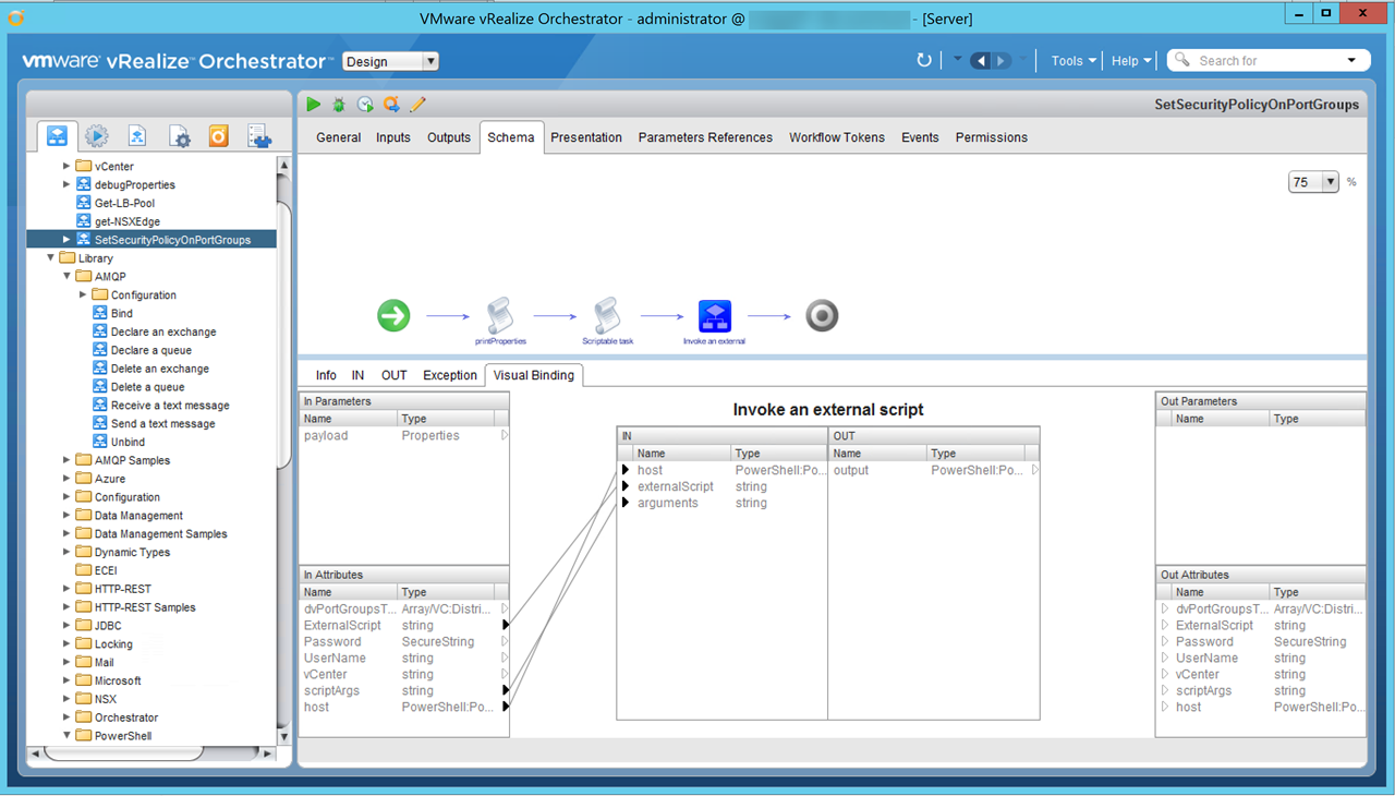
Figure25 – SetSecurityPolicyOnPortGroups Workflow – Visual Bindings from script to external script
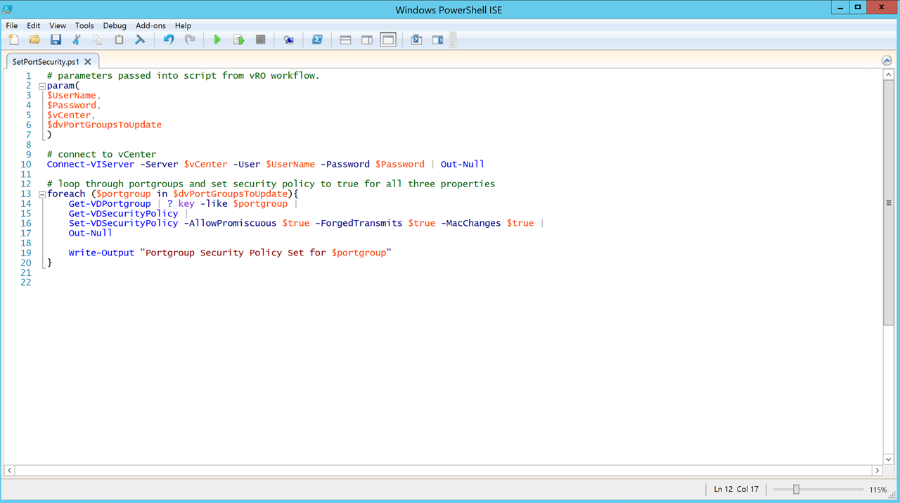
Figure26 – SetSecurityPolicyOnPortGroups Workflow – PowerCLI script used to change security policy settings on discovered port groups.
* Create an Event Subscription making sure to define conditions, select workflow (SetSecurityPolicyOnPortGroups) and enable blocking.
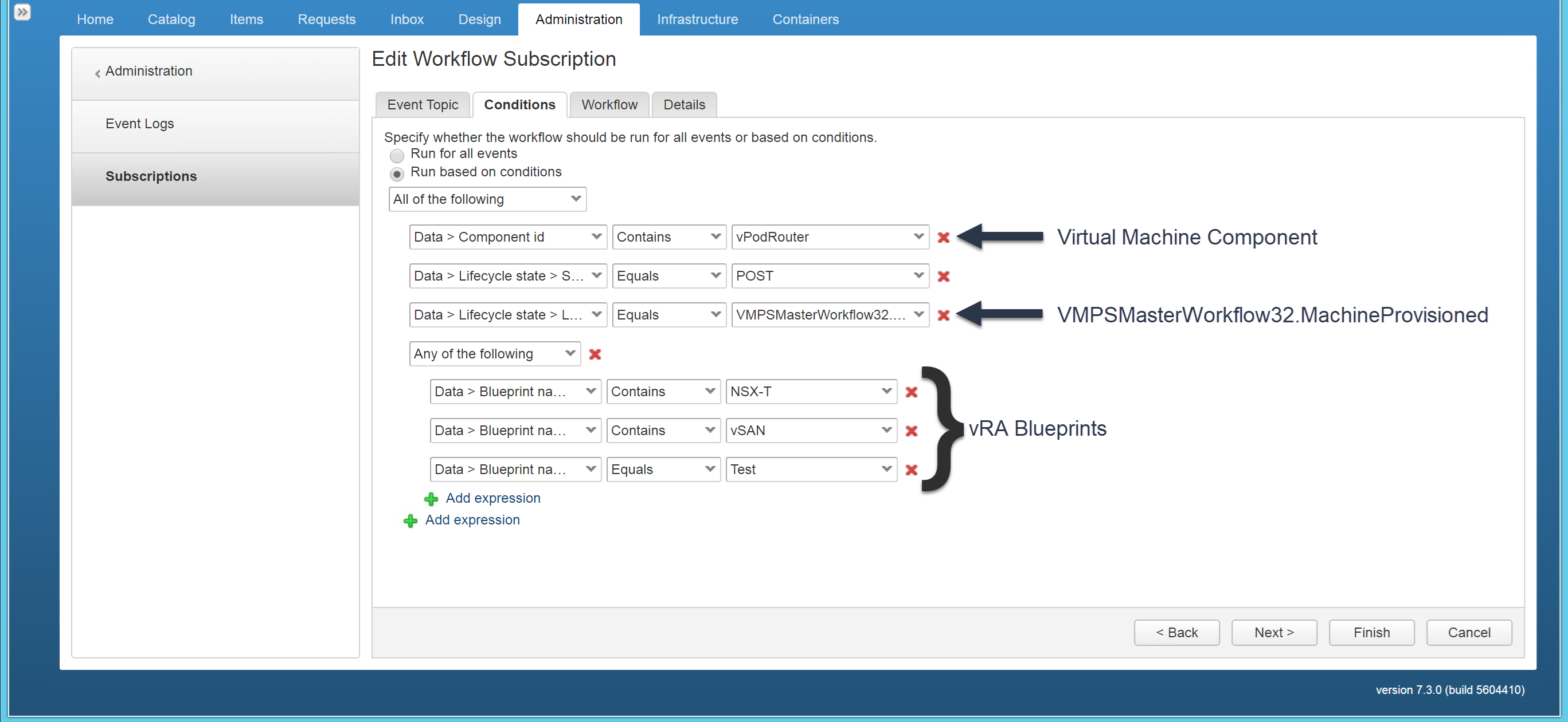
Figure27 – Event Subscription conditions. Only need to affect the vPodRouter logical switches (port groups) as all virtual traffic flows on these two networks.
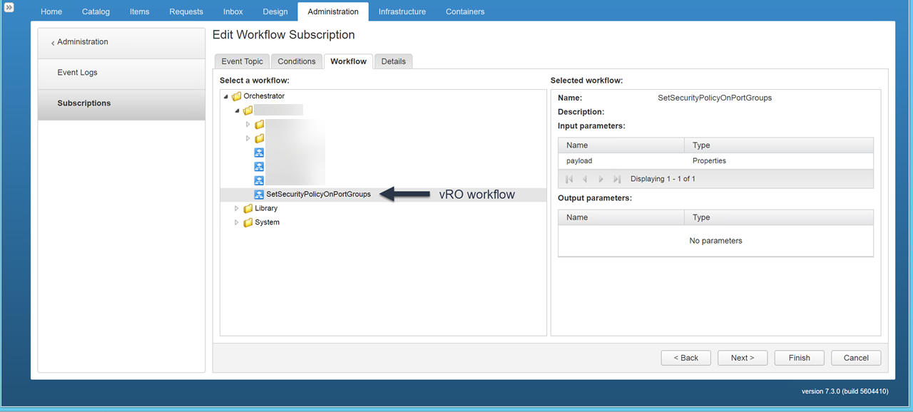
Figure28 – Select vRO workflows to execute
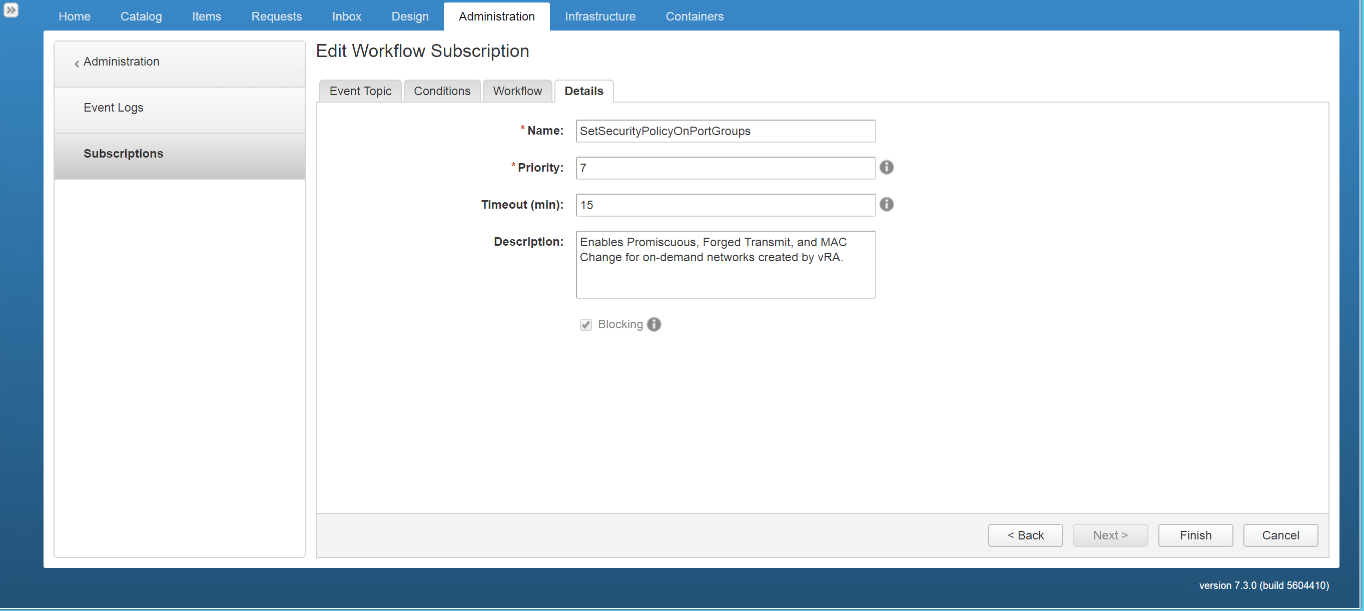
Figure29 – Set blocking and define priority
Confirm workflow executed successfully and settings have been changed.
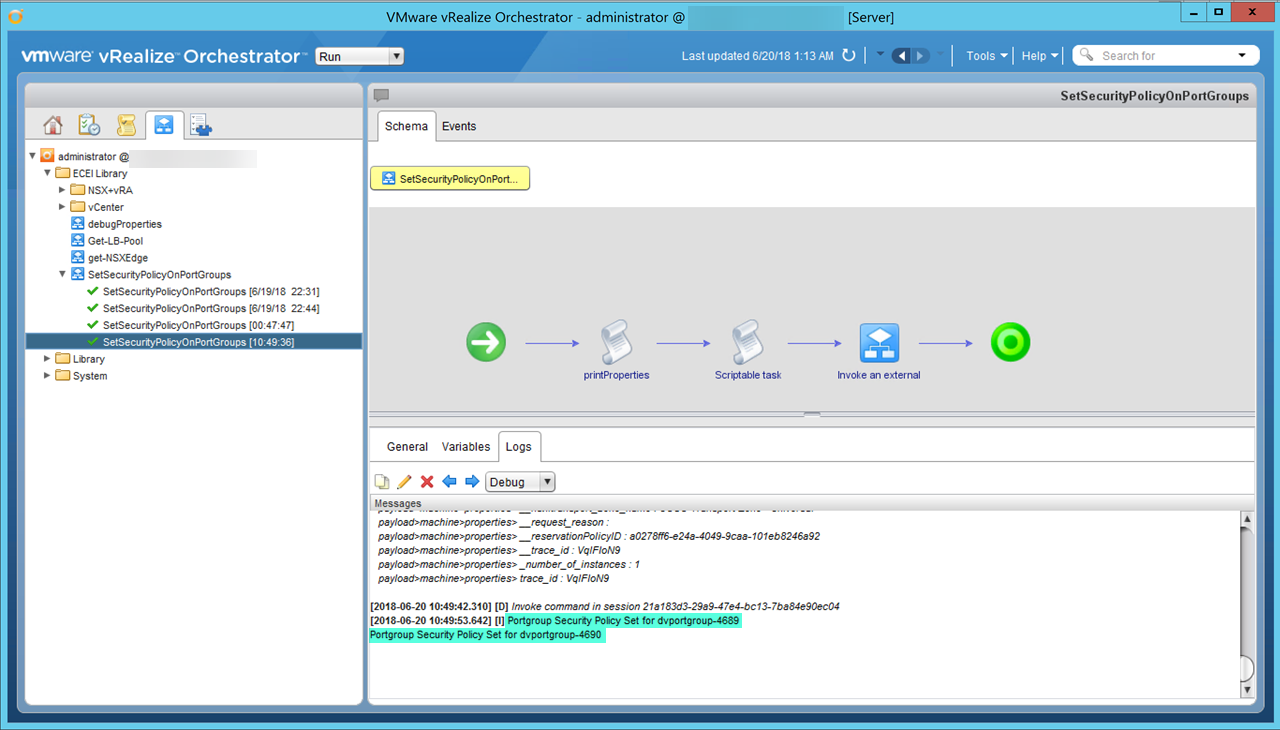
Figure30 – vRO workflow success
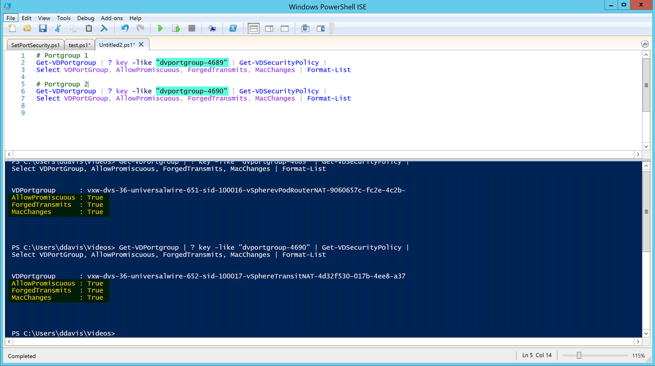
Figure31 – Validate via PowerCLI
Publishing Time
Our blueprint is ready to be published simply click Finish and click Publish (Figure21).
In order to be selectable from the catalog, we need to associate the blueprint with a service assuming Service and Entitlements have already been set up. Navigate to Administration > Catalog Items > Select NSX-T Environment > Configure > Service. In my case, the service is called “VMware [Nested]”.
Note: You can also add an icon here for your blueprint. 😉
If we go to our catalog > VMware [Nested] we should see our new shiny blueprint (Figure22). In our environment, this blueprint takes an hour to deploy (Figure23).
FYI the Blueprint name is “[NAT] NSX-T Environment” is the original blueprint. The “NSX-T Environment” blueprint was created for this post as you can see it’s a popular one (Figure24). 😉
To access the environment I simply get the IP address for the nsxt-controlcenter from the Items tab (Figure25).

Figure32 – NSX-T Environment blueprint published
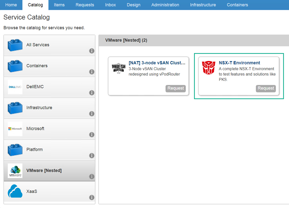
Figure33 – Published NSX-T Blueprint

Figure34 – Deployment Time

Figure35 – Popular Blueprint

Figure36 – Get IP Address
Results
Below are screenshots of various components vSphere, NSX-T, and PKS (Figure37 -Figure41). This has been an awesome learning experience I hope you enjoyed the two posts series on developing an NSX-T blueprint in vRealize Automation.
If your interested in seeing a video demonstration of the vRA/NSX-T environment just leave a comment below and I’d be happy to put something together.
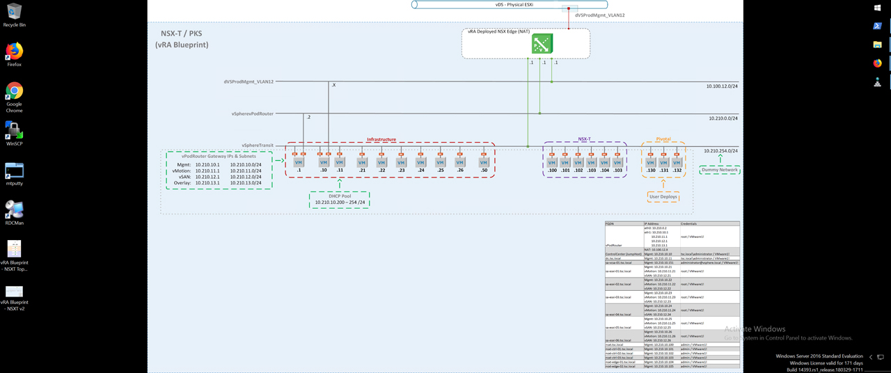
Figure37 – ControlCenter Desktop
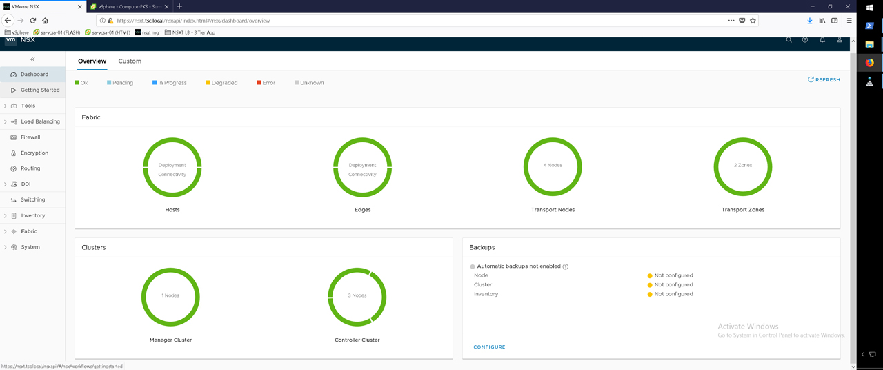
Figure38 – NSX-T Dashboard
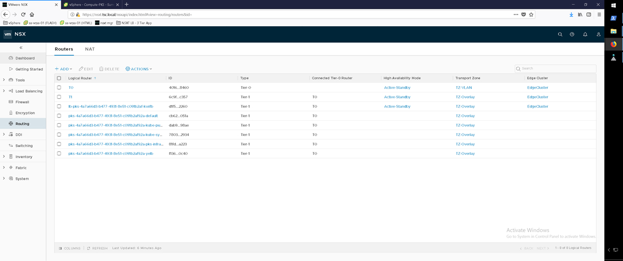
Figure39 – NSX-T Routers
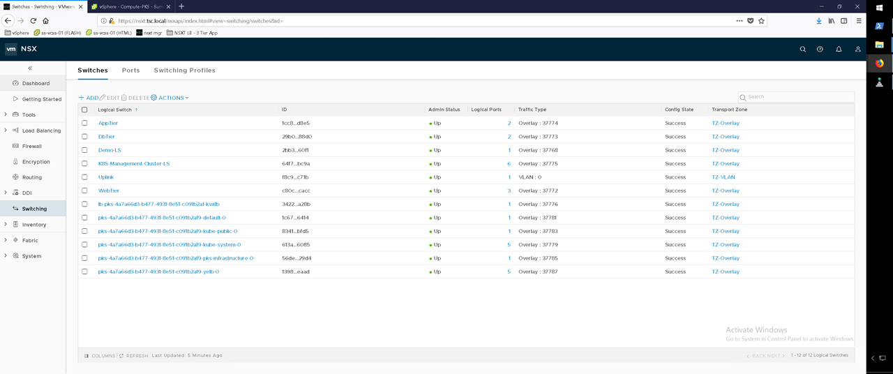
Figure40 – NSX-T Switches
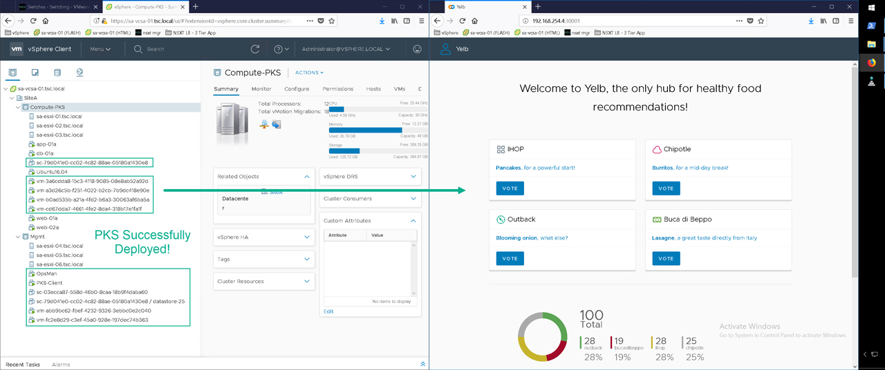
Figure41 – vCenter and PKS components deployed with a functional application
Subscribe to my newsletter
Read articles from Dave Davis directly inside your inbox. Subscribe to the newsletter, and don't miss out.
Written by
