Navigating Networking Layers: The Journey of Data Through TCP
 Siddhartha S
Introduction
As backend engineers, we often take many things for granted without even realizing it, particularly what's happening beneath the surface. Although application programmers may not need to understand these underlying processes, architects must grasp the internals. This understanding is crucial for several reasons:
Choice of tools
Designing the data flow for the system
Estimating costs
Extensibility of the system
Failing to properly assess any of these factors can lead to significant losses in time and cost, as well as challenging system maintenance.
When making an HTTP call, numerous processes occur behind the scenes. Your data is transformed from JSON to bytes, to segments, to packets, to data frames, and finally, to radio waves or electrical signals.
In this article, I aim to demystify the journey of an HTTP call to a remote server. As a bonus, we will also explore the differences between Application Load Balancers (ALB) and Network Load Balancers (NLB) in AWS. We will examine the cost differences between these AWS offerings with our newly acquired knowledge.
Traveling through the layers of network
Most of us are probably familiar with the OSI model of networking. However, it often remains an academic concept in our minds. Visualizing how data travels and transforms through the various network layers can be challenging. Revisiting the OSI model is a good starting point, but this time let's focus on visualizing how the data transforms.
The accompanying diagram explains how a request travels from the sender (typically the client) to the receiver (typically the server). It assumes that the receiver’s IP address and ports are known. If the IP address and port of the receiver are unknown, an additional DNS request is needed to resolve the IP address.
curl to retrieve the results. For example, the IP address and port for my domain can be readily located:Before delving into the diagram, two points are worth noting:
The layers are logical, not physical, and should be viewed as such.
The processes aren't strictly separated. Routers and switches may perform operations associated with other layers. For example, many routers (layer 3) also function as switches (layer 2). More on this later.
The application code resides at the application layer, where a fetch call is made to a Node.js API or another technology. The fetch request includes the IP, port, and request object, which is a JSON object.
At the presentation layer, the request object is transformed into bytes.
The bytes and host port information are sent to another API call in the session layer, which maintains the state of the connection as it forms in the following layer.
Now the flow enters the OS level. Each OS implements its handling from the transport layer, where a TCP connection is established with the receiver. TCP data can only be passed if a valid connection exists, meaning both sender and receiver operating systems maintain the state for integral data transmission over TCP. Data is broken into SEGMENTS, with headers marked on all segments, containing all flags and data necessary for TCP communication and maintaining data integrity. Understanding the TCP header in detail is a topic for another article.
In the network layer, segments are turned into IP PACKETS, containing the receiver IP address. The port information remains within the segments inside the IP packets. These packets are then passed into another API call that takes them to the data frame layer.
The data frame layer packages IP packets into data FRAMES, which include MAC addresses the frame should be forwarded to. In this case, it's the sender router’s MAC address.
The physical layer transmits data frames as radio waves (Wi-Fi) or light signals (optical fiber) to the sender router.
The sender router checks the data frame and underlying IP packet, recognizing the recipient IP is meant for a distant server. It performs Network Address Translation (NAT), replacing the sender’s IP and port with its public IP and a port. To perform NAT, routers need access to layer 4 data (ports), hence they operate from layer 4 to 2.
After several hops across ISPs and routers, the frame reaches the destination network and its gateway, the receiver router.
The receiver router checks its NAT table to determine the internal host and port for the request, and consults the ARP table for the server's MAC address.
The router forwards the request to the correct receiver, which extracts the IP packets from the data frames and the segments from the IP Packets, then handles the TCP segments using the port specified to deliver data to the appropriate program.
The response from the receiver travels back via a similar route. Hence, I use 'sender' and 'receiver' instead of 'client' and 'server.'
You may wonder why terms like segments, packets, and frames are emphasized. This is to highlight:
Segments for TCP
Packets for IP
Frames for Data
These elements fit together like Matryoshka dolls.

Questions like what NAT Tables and ARP Tables are, and how NAT works, will be explored in another article. For the OSI model and data transformation across layers, understanding the data transformation is key. Details about the nuances of network data travel will be addressed later.
Load balancers: NLB vs ALB
Load balancers function as reverse proxies with the added capability of distributing traffic efficiently across instances of services. Having already explored the various layers of the OSI model and how data transforms as it travels through them, we are well-equipped to understand the differences between Network Load Balancers and Application Load Balancers. This comprehension will also help us grasp why their costs differ among AWS offerings.
Network Load Balancers (NLB)
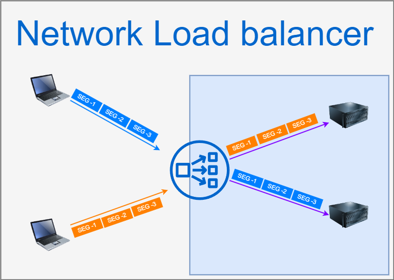
NLB operate at Layer 4 of the OSI model, which means they primarily manage connections and segments. As illustrated in the accompanying diagram, when clients establish TCP connections with the load balancer, the segments are transmitted without the network being aware of the entire request that these segments make up. Consequently, the load balancing operation is inherently sticky, meaning that all segments from a given connection are directed to a specific server. For example, all blue segments are paired with one server, while all orange segments correspond to another (refer following diagram). Additionally, since NLBs lack visibility into higher-layer data, they do not support caching or advanced routing functionalities, making them purely focused on load balancing while ensuring security by not exposing higher layer information.

Pros:
Simple and efficient for distributing traffic based on TCP connections.
High performance with low latency.
Secure, as it doesn’t handle higher-layer payloads.
Cons:
Limited to Layer 4; lacks visibility into application-level data.
No caching support or advanced routing capabilities.
Sticky sessions by default, which may not suit all applications.
Application Load Balancers (ALB)
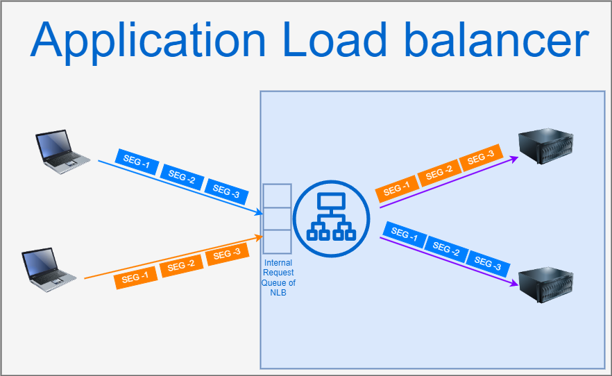
ALBs, in contrast, function at Layer 7 of the OSI model, allowing them to analyze the entire incoming request. As shown in the figure, ALBs maintain a buffer and act as independent receivers of segments, which enables them to implement smart routing capabilities based on specific request route keys. This capability enhances their efficiency in directing traffic to appropriate service clusters. Moreover, ALBs can also perform TLS offloading, necessitating the management of TLS certificates, which some may view as a potential security risk. Unlike NLBs, ALBs can provide caching support, further optimizing the handling of incoming requests.

Pros:
Operates at Layer 7, enabling detailed inspection of requests for smart routing.
Provides caching support, enhancing response times.
Capable of performing TLS offloading, improving security management.
Cons:
More complex and may introduce additional latency due to extensive processing.
Requires management of TLS certificates, which can pose a security risk if not handled properly.
Potentially higher costs compared to NLBs due to more advanced features.
OS facilitating TCP connection under the hood
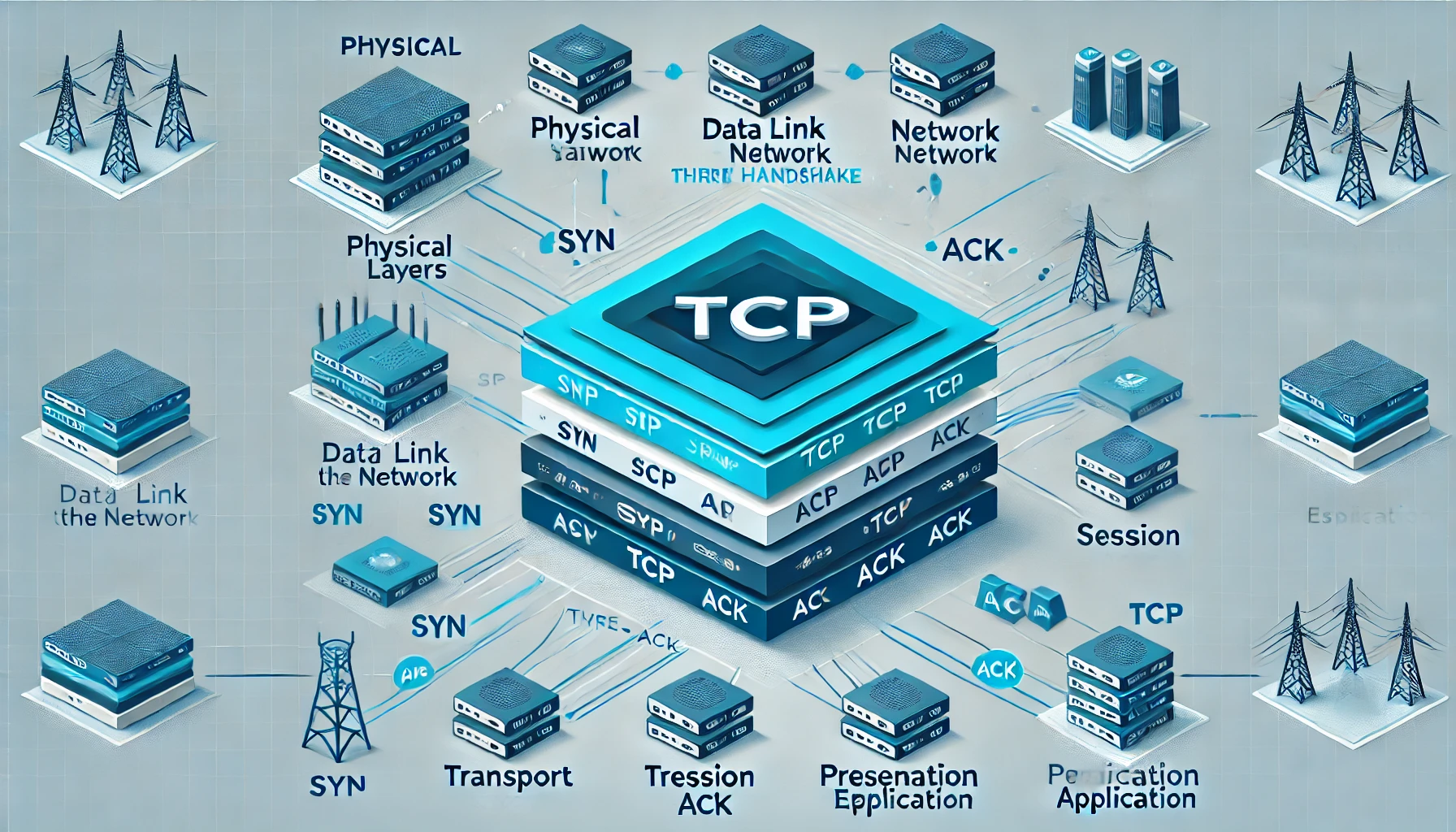
A TCP connection is established through a three-way handshake that consists of SYN, SYN-ACK, and ACK requests. The SYN represents the synchronization of the client’s initial sequence number for transmission.
The diagram below illustrates the connection establishment process. This is a well-known fact, and you are likely already familiar with it.
Client                               Server
   |                                       |
   | ---------------- SYN ---------------> |
   |                                       |
   | <-------------- SYN-ACK ------------- |
   |                                       |
   | ---------------- ACK ---------------> |
   |                                       |
   | <-------- Connection Established ---- |
   |                                       |
The interesting part lies in understanding what happens under the hood in the server’s operating system while these SYN and ACK requests are exchanged. After several attempts to write this explanation, I decided to create a comic strip to illustrate the process. I believe that following the comic strip while reading along will enhance comprehension. Additionally, we will correlate this process with high-level code for easier familiarity with our everyday coding experience.
Let's first discuss the server processes starting up in the OS. It’s quite common for a single server to run multiple server programs listening on different ports. For instance, two processes—Process-1 and Process-2—could start on ports 3000 and 8000, respectively. The Node.js code to initiate these server programs would look like this:
// Import the required modules from Node.js
const http = require('http');

// Create the first server instance for handling HTTP requests on port 3000
const process1Server = http.createServer((req, res) => {
    // Process incoming requests for this server
    res.end('Hello from Process 1 on port 3000!');
});

// Creating the second server instance for handling WebSocket connections on port 8000
const process2Server = http.createServer((req, res) => {
    // Process incoming requests for this server
    res.end('Hello from Process 2 on port 8000!');
});

// Making the first server listen on port 3000
process1Server.listen(3000, "192.168.0.5", () => {
    console.log('Server is listening on port 3000');
});

// Making the second server listen on port 8000
process2Server.listen(8000, "192.168.0.5", () => {
    console.log('Server is listening on port 8000');
});
With the call to the
listen()method, Node.js makes internal system calls to create sockets bound to the addresses 192.168.0.5:3000 and 192.168.0.5:8000, respectively. For each socket, file descriptors are created. Sockets can be thought of as files, and file descriptors serve as identifiers for those files.The OS maintains two queues: the SYN queue (also known as the half-connection queue) and the accept queue. When a SYN request arrives from a client, the OS immediately sends back a SYN-ACK to the client. the OS creates an entry in the SYN queue containing the following details:
Sender Address
Sender Port
Receiver Address (in this case, 192.168.0.5)
Receiver Port (in this case, 3000)
Client’s Initial Sequence Number
The client then sends an ACK, at which point the entry in the SYN queue is moved to the accept queue.
The accept queue is a data structure that server processes monitor closely, often utilizing a mutex. They repeatedly call
accept()on its entries.In this example, Process-2, which has the file descriptor for the socket created for 192.168.0.5:8000, attempts to call accept() on the entry. However, the OS checks and denies the request because the entry corresponds to 192.168.0.5:3000.
Next, Process-1 calls accept() successfully, as its file descriptor matches the entry in the queue. At this point, the OS creates a new socket and file descriptor for this connection using the data from the accept queue entry:
Sender Address
Sender Port
Receiver Address (in this case, 192.168.0.5)
Receiver Port (in this case, 3000).
The OS then hands over this socket to Process-1, which now has all the necessary details for communication between the client and the server.
Conclusion
This article has provided an in-depth look at the layers of networking and the process of creating a TCP connection. If you've learned something new from this discussion, you likely recognize the high cost of network calls and may already be considering ways to minimize them. Truly understanding the intricacies of network calls often leads to reservations about adopting a Microservices Architecture, as it inherently involves an increase in network calls, which can introduce complexity and latency.
While this article explores various concepts in detail, it inevitably leaves many questions unanswered. For instance, although we examined the journey of data from sender to receiver, we only touched on the ideas of ARP and NAT without fully elaborating on them. Additionally, while we discussed TCP connection establishment, TCP encompasses much more than just this aspect. How does it guarantee data integrity? How does it regulate the flow of data between sender and receiver? After all, TCP has been a foundational protocol for nearly 40 years and continues to underpin many of the major network communications we rely on today.
In future articles, we will work to clarify these remaining details and further demystify the complexities of networking.
Subscribe to my newsletter
Read articles from Siddhartha S directly inside your inbox. Subscribe to the newsletter, and don't miss out.
Written by

Siddhartha S
Siddhartha S
With over 18 years of experience in IT, I specialize in designing and building powerful, scalable solutions using a wide range of technologies like JavaScript, .NET, C#, React, Next.js, Golang, AWS, Networking, Databases, DevOps, Kubernetes, and Docker. My career has taken me through various industries, including Manufacturing and Media, but for the last 10 years, I’ve focused on delivering cutting-edge solutions in the Finance sector. As an application architect, I combine cloud expertise with a deep understanding of systems to create solutions that are not only built for today but prepared for tomorrow. My diverse technical background allows me to connect development and infrastructure seamlessly, ensuring businesses can innovate and scale effectively. I’m passionate about creating architectures that are secure, resilient, and efficient—solutions that help businesses turn ideas into reality while staying future-ready.