Building a Secure Lora Gateway using Zymbit SEN400
 David G. Simmons
Overview
This How To Guide will show you how to integrate a LoRaWAN card with a Zymbit Secure Edge Node (SEN) Developer Kit. The Goals is to be able to get your Zymbit Secure Edge Node Developer Kit to come up as a LoRaWAN packet forwarder and connect to The Things Network as a LoRaWAN Gateway device.
The Zymbit SEN Developer Kit contains a Raspberry Pi Secure Compute Module (SCM) running Linux (in this case, Raspberry Pi OS). The SCM is a hardened Linux computer that provides a secure element for the Raspberry Pi compute node. The LoRaWAN card is a low-power, long-range wireless communication card that allows you to connect your Raspberry Pi to a LoRaWAN network.
Here is a tl;dr of the steps we will take to create a Secure Edge Node with a LoRA communications card as a data path:
Assemble the LoRA Pi HAT and connect it to the Secure Edge Node
Install the SX1302 Hardware Abstraction Layer (HAL) software on the SEN
Configure the LoRa software to connect the modem to the network
Install & configure Bootware™ on the SEN to manage secure boot, filesystem encryption, AB partitions and recovery
Why are we doing this?
Great question! One f the great things about LoRa is the, well, LoRa part: Long Range. What that usually means is that the device will be deployed somewhere fairly remote. And remote assets are more vulnerable to being tampered with. We don’t want our device, or the communications from the device, tampered with.
Parts list
Here are all the parts you’ll need in order to complete this turorial:
A LoRaWAN card Make sure you get one for your Geography as a North American version uses an entirely different frequency than the European version. This integration is for this specific LoRaWan card.
A PiHAT adapter for the LoRaWAN card
An antenna (for example. Make sure you get one that is tuned to your LoRaWAN card frequency!)
Hardware setup
If you’ve ordered the parts from the list above, here’s what you you’ll get.
Zymbit Secure Edge Node Developer Kit
The Zymbit Secure Edge Node Developer kit (DevKit) arrives in 3 parts
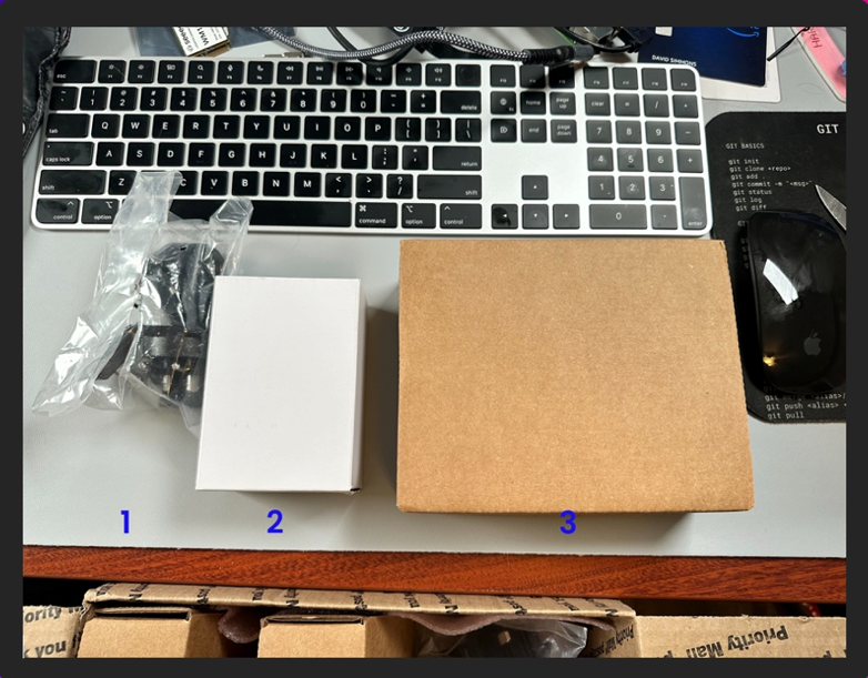
The parts bag contains all the adapters you will need for your country’s power outlet.
The smaller white box is the power adapter
The larger brown box is the DevKit and associated parts.
Once you unbox (or unbag) all those, your DevKit should look something like this:
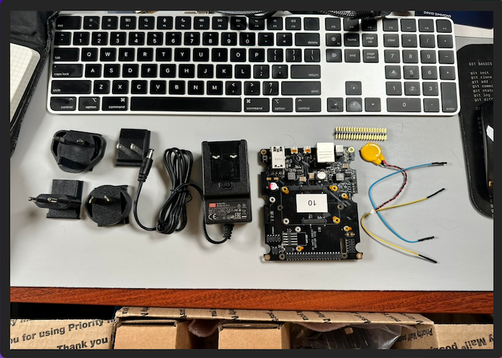
Note that the Developer Kit comes with a couple of Jumper Wires (which you won’t need for this), a small battery, and a set of header pins.
LoRaWAN card
The LoRaWAN card comes in a small box with the card itself and the Pi HAT adapter.
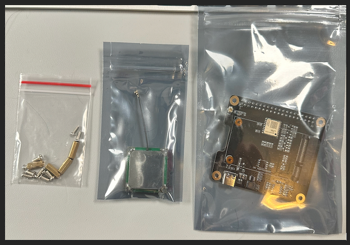
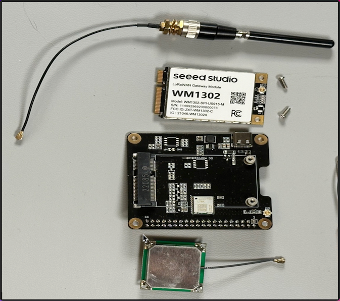
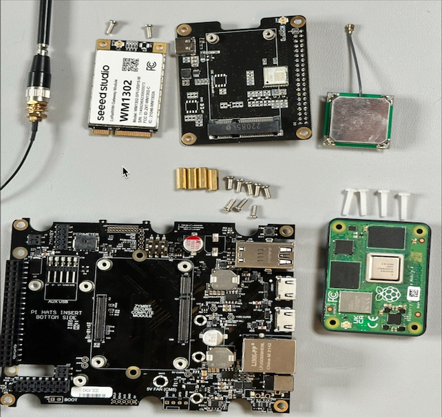
The kit comes with a GPS antenna, a LoRaWAN card, and the Pi HAT adapter. Note that it does not come with the LoRa antenna, so you’ll need to order that separately . It comes with all the screws and stand-offs that you need to attach the card to the Pi HAT and the Pi Hat to the board.
Hardware Assembly
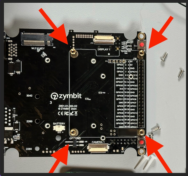
The first thing to do is to attach the standoffs for the Pi HAT to the board. You will need to do this before you attach the SCM to the board, as the holes are not accessible once the SCM is attached
Use the four large brass standoffs and 4 of the screws to attach the standoffs to the main board
Now you can turn the board over and install the Secure Compute Module (SCM) onto the board.
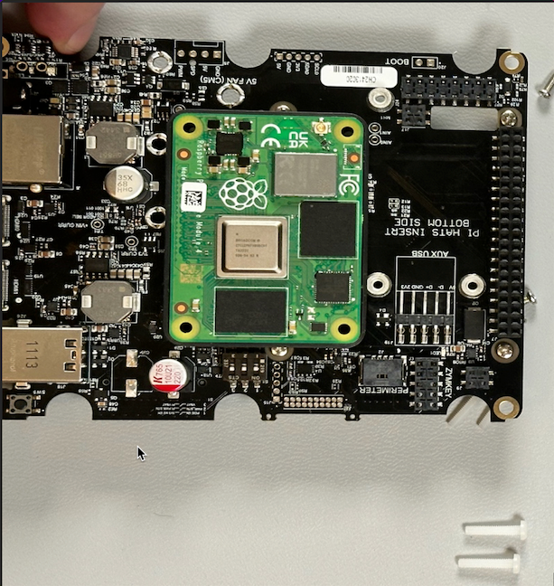
Make sure that the SCM is securely seated before proceeding.
Once you have connected the SCM to the board (you should hear a couple of clicks as the connectors seat fully), you can secure the SCM to the motherboard with the 4 provided nylon screws.
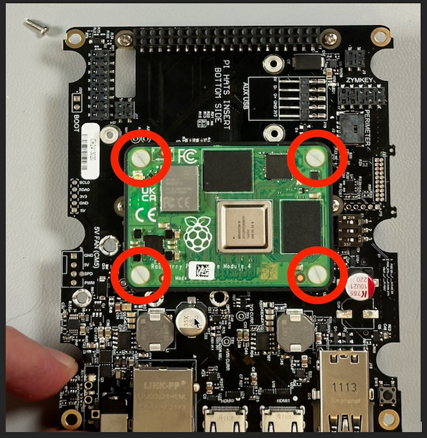
Now it’s time to turn the board over again and install the Pi HAT on the bottom.
First, take the set of header pins and insert them into the Board. This will allow you to seat the Pi HAT onto the pins.
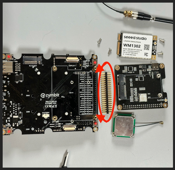
Once the pins are completely seated, you can attach the Pi HAT to the board. Make sure that all the pins line up and that the board is completely seated, then use the provided screws to secure the Pi HAT to the board.
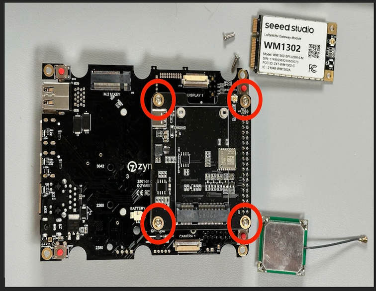
Attach the GPS module to the Pi HAT. This can be a difficult connector to get seated, so be patient and make sure it’s completely seated.
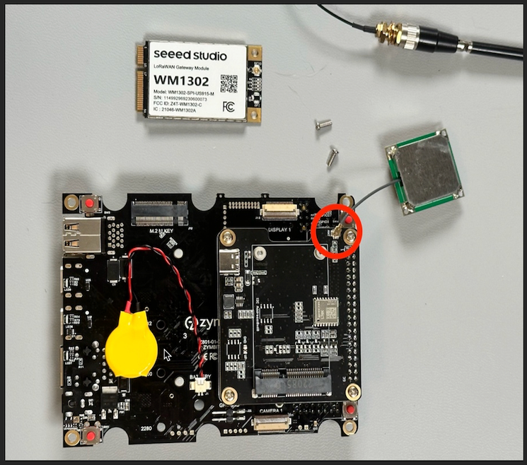
Before putting the LoRaWAN card on the Pi HAT, you’ll need to attach the antenna to the card. Do this before installing the card on the PiHat as it can take a bit of force to properly seat the antenna connector. Like the GPS antenna, this can be tricky to seat correctly so be careful, but make sure it’s completely seated.
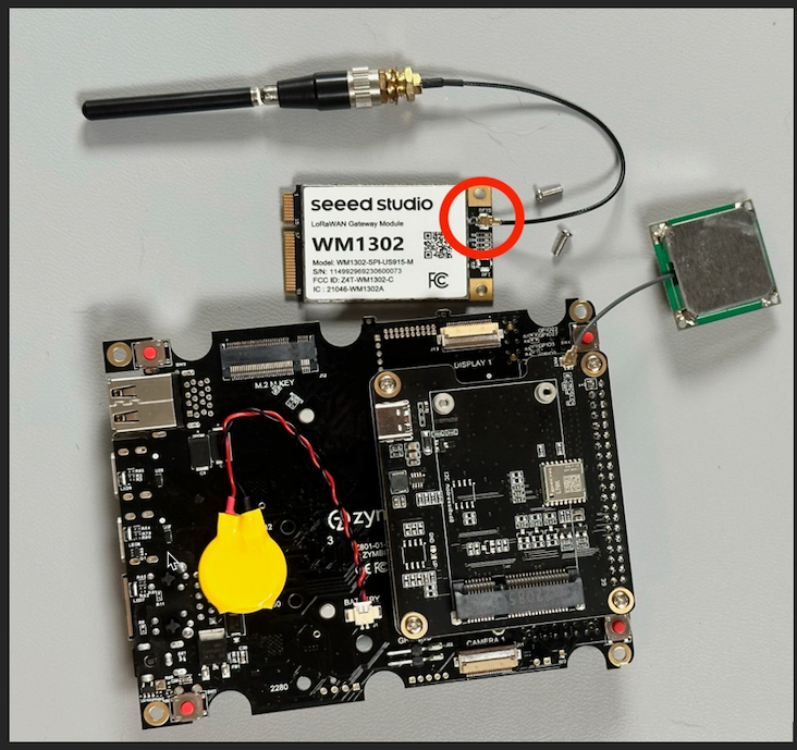
Finally, you can attach the LoRaWAN card to the Pi HAT. Slide the LoRaWAN card into the PCIe slot on the Pi HAT and then secure it with the provided screws.
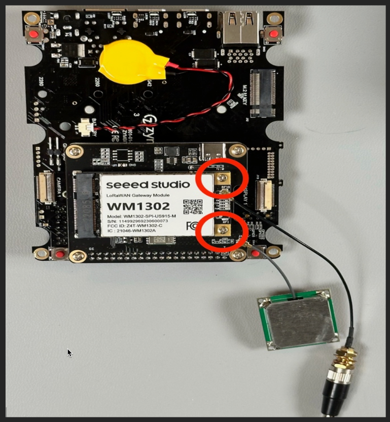
The hardware is now assembled and it’s time to move on to the software.
Software setup
Note: I will not be going into the details of setting up the SCM itself. If you’d like detailed information, you can always find it in our documentation. As long as you have attached it correctly, and attached an ethernet cable to the board, you should be able to login to the SCM with:
ssh zymbit@zymbit-dev.local
Use the password zymbit to login, but you should immediately change it to something secure using the passwd command.
passwd
You will be prompted to enter the current password, and then the new password twice.
Setting up the LoRaWAN card
The first thing you’ll need to do is to install the sx1302_hal software on your SCM. This software is required to communicate with the LoRaWAN card. The complete instructions for setting up the software can be found here, but I’ll provide a brief overview here.
git clone https://github.com/Lora-net/sx1302_hal.git
cd sx1302_hal
make clean all
This should give you a directory structure similar to:
├── libloragw
│   ├── libloragw.a
│   ├── library.cfg
│   ├── readme.md
│   ├── src
│   ├── test_loragw_cal_sx125x
│   ├── test_loragw_capture_ram
│   ├── test_loragw_com
│   ├── test_loragw_com_sx1250
│   ├── test_loragw_com_sx1261
│   ├── test_loragw_counter
│   ├── test_loragw_gps
│   ├── test_loragw_hal_rx
│   ├── test_loragw_hal_tx
│   ├── test_loragw_i2c
│   ├── test_loragw_reg
│   ├── test_loragw_sx1261_rssi
│   ├── test_loragw_toa
│   └── tst
├── libtools
│   ├── inc
│   ├── libbase64.a
│   ├── libparson.a
│   ├── libtinymt32.a
├── LICENSE.TXT
├── Makefile
├── mcu_bin
│   └── rlz_010000_CoreCell_USB.bin
├── packet_forwarder
│   ├── global_conf.json
│   ├── global_conf.json.sx1250.AS923.USB
│   ├── global_conf.json.sx1250.CN490
│   ├── global_conf.json.sx1250.CN490.USB
│   ├── global_conf.json.sx1250.EU868
│   ├── global_conf.json.sx1250.EU868.USB
│   ├── global_conf.json.sx1250.US915
│   ├── global_conf.json.sx1250.US915.USB
│   ├── global_conf.json.sx1255.CN490.full-duplex
│   ├── global_conf.json.sx1257.EU868
│   ├── inc
│   ├── lora_pkt_fwd
│   ├── PROTOCOL.md
│   ├── readme.md
│   └── src
├── readme.md
├── target.cfg
├── tools
│   ├── node-red-registers.json
│   ├── payload_tools
│   ├── reset_lgw.gpiod.sh
│   ├── reset_lgw.gpiod.sh.tar.gz
│   ├── reset_lgw.sh
│   └── system
├── util_boot
│   ├── boot
│   ├── Makefile
│   ├── obj
│   ├── readme.md
│   └── src
├── util_chip_id
│   ├── chip_id
│   ├── Makefile
│   ├── obj
│   ├── readme.md
│   ├── reset_lgw.sh
│   └── src
├── util_net_downlink
│   ├── Makefile
│   ├── net_downlink
│   ├── obj
│   ├── readme.md
│   └── src
├── util_spectral_scan
│   ├── Makefile
│   ├── obj
│   ├── plot_rssi_histogram.py
│   ├── readme.md
│   ├── spectral_scan
│   └── src
└── VERSION
You will need to edit the reset_lgw.sh file in the tools directory and make the following changes:
# GPIO mapping has to be adapted with HW
GPIO_CHIP=gpiochip0
GPIO_PIN_SX1302_RESET=17     # SX1302 reset
GPIO_PIN_SX1302_POWER_EN=18  # SX1302 power enable
GPIO_PIN_SX1261_RESET=5     # SX1261 reset (LBT / Spectral Scan)
GPIO_PIN_AD5338R_RESET=13    # AD5338R reset (full-duplex CN490 reference design)
Note: With the latest versions of Linux for Raspberry Pi there has been a change in how GPIO pins are referenced, and this configuration reflects that change. It is based on the patch for sx1302_hal referenced in this comment. I highly recomment downloading that patch and using that version, especially if you are running Bookworm
Once you have made those changes to the reset_lgw.sh script, you need to copy it into the packet_forwarder, util_chip, and libloragw directories.
You now should have a fully functional LoRaWAN concentrator, but at this point, you cannot communicate with any network with it, since we haven’t set up any upstream LoRaWAN network.
Connecting to The Things Network
There are, of course, other LoRaWAN networks out there, but since I already have an existing account with TheThingsNetwork, I am using that network.
Once you have logged in to your account at TheThingsNetwork, go to your console and create a new Gateway. You’ll need an EUI for your gateway, and the most common practice is to use the LoRa concentrator Chip ID for this.

On your SCN, run:
cd sx1302_hal/util_chip
./chip_id
You should see output similar to:
$ ./chip_id
CoreCell reset through GPIO17...
SX1261 reset through GPIO17...
CoreCell power enable through GPIO18...
CoreCell ADC reset through GPIO13...
Opening SPI communication interface
Note: chip version is 0x10 (v1.0)
INFO: using legacy timestamp
ARB: dual demodulation disabled for all SF
INFO: found temperature sensor on port 0x39
INFO: concentrator EUI: 0x0016c001f11172be
Closing SPI communication interface
CoreCell reset through GPIO17...
SX1261 reset through GPIO17...
CoreCell power enable through GPIO18...
CoreCell ADC reset through GPIO13...
This tells you that your board is actually working, and gives you the EUI of the chip, which you will enter into the form to create your gateway.
Don’t worry about the warning, just click the button to convert the MAC to an EUI and it will be fine.
You should now have a properly configured (but off-line) gateway:
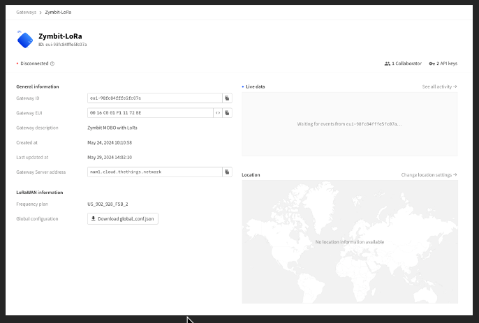
Now it’s time to configure your gateway to connect to the network.
Connecting to the network
In order to connect to The Things Network you will need to add the credentials from configuring the gateway device to the configuration files on the SCM.
This configuration file is located in the packet_forwarder directory and you will choose the one that matches your frequency plan and card model. Since I am in the US, and using the SEEED WM1302 on a Pi HAT (not via USB) I will be editing the global_conf.json.sx1250.US915 file. Near the end of the file, look for the gateway_conf section and change them to the settings you see on your Gateway Page at The Things Network:
"gateway_conf": {
        "gateway_ID": "0016c001f11172be",
        /* change with default server address/ports */
        "server_address": "nam1.cloud.thethings.network",
        "serv_port_up": 1700,
        "serv_port_down": 1700,
If you clicked the “Download global_conf.json” button, you can also find these values in that file.
Once you’ve made these changes, save the file, and start your packet forwarder:
cd packet_forwarder
./lora_pkt_fwd -c global_conf.json.sx1250.US915
Note that I’m using the configuration file that I just edited. If you used a different configuration file, you’ll need to use that one.
You should see output from the LoRaWAN concentrator:
$ ./lora_pkt_fwd -c global_conf.json.sx1250.US915
*** Packet Forwarder ***
Version: 2.1.0
*** SX1302 HAL library version info ***
Version: 2.1.0;
***
INFO: Little endian host
INFO: found configuration file global_conf.json.sx1250.US915, parsing it
INFO: global_conf.json.sx1250.US915 does contain a JSON object named SX130x_conf, parsing SX1302 parameters
INFO: com_type SPI, com_path /dev/spidev0.0, lorawan_public 1, clksrc 0, full_duplex 0
INFO: antenna_gain 0 dBi
INFO: Configuring legacy timestamp
INFO: Configuring Tx Gain LUT for rf_chain 0 with 16 indexes for sx1250
INFO: radio 0 enabled (type SX1250), center frequency 904300000, RSSI offset -215.399994, tx enabled 1, single input mode 0
INFO: radio 1 enabled (type SX1250), center frequency 905000000, RSSI offset -215.399994, tx enabled 0, single input mode 0
INFO: Lora multi-SF channel 0>  radio 0, IF -400000 Hz, 125 kHz bw, SF 5 to 12
INFO: Lora multi-SF channel 1>  radio 0, IF -200000 Hz, 125 kHz bw, SF 5 to 12
INFO: Lora multi-SF channel 2>  radio 0, IF 0 Hz, 125 kHz bw, SF 5 to 12
INFO: Lora multi-SF channel 3>  radio 0, IF 200000 Hz, 125 kHz bw, SF 5 to 12
INFO: Lora multi-SF channel 4>  radio 1, IF -300000 Hz, 125 kHz bw, SF 5 to 12
INFO: Lora multi-SF channel 5>  radio 1, IF -100000 Hz, 125 kHz bw, SF 5 to 12
INFO: Lora multi-SF channel 6>  radio 1, IF 100000 Hz, 125 kHz bw, SF 5 to 12
INFO: Lora multi-SF channel 7>  radio 1, IF 300000 Hz, 125 kHz bw, SF 5 to 12
INFO: Lora std channel> radio 0, IF 300000 Hz, 500000 Hz bw, SF 8, Explicit header
INFO: FSK channel 8 disabled
INFO: global_conf.json.sx1250.US915 does contain a JSON object named gateway_conf, parsing gateway parameters
INFO: gateway MAC address is configured to 0016C001F11172BE
INFO: server hostname or IP address is configured to "nam1.cloud.thethings.network"
INFO: upstream port is configured to "1700"
INFO: downstream port is configured to "1700"
INFO: downstream keep-alive interval is configured to 10 seconds
INFO: statistics display interval is configured to 30 seconds
INFO: upstream PUSH_DATA time-out is configured to 100 ms
INFO: packets received with a valid CRC will be forwarded
INFO: packets received with a CRC error will NOT be forwarded
INFO: packets received with no CRC will NOT be forwarded
INFO: GPS serial port path is configured to "/dev/ttyS0"
INFO: Reference latitude is configured to 3541.643360 deg
INFO: Reference longitude is configured to 7846.760580 deg
INFO: Reference altitude is configured to 133 meters
INFO: Beaconing period is configured to 0 seconds
INFO: Beaconing signal will be emitted at 869525000 Hz
INFO: Beaconing datarate is set to SF9
INFO: Beaconing modulation bandwidth is set to 125000Hz
INFO: Beaconing TX power is set to 14dBm
INFO: Beaconing information descriptor is set to 0
INFO: global_conf.json.sx1250.US915 does contain a JSON object named debug_conf, parsing debug parameters
INFO: got 2 debug reference payload
INFO: reference payload ID 0 is 0xCAFE1234
INFO: reference payload ID 1 is 0xCAFE2345
INFO: setting debug log file name to loragw_hal.log
INFO: [main] TTY port /dev/ttyS0 open for GPS synchronization
CoreCell power enable on through GPIO18...
CoreCell reset through GPIO17...
SX1261 reset through GPIO5...
CoreCell ADC reset through GPIO13...
Opening SPI communication interface
Note: chip version is 0x10 (v1.0)
INFO: using legacy timestamp
INFO: LoRa Service modem: configuring preamble size to 8 symbols
ARB: dual demodulation disabled for all SF
INFO: found temperature sensor on port 0x39
INFO: [main] concentrator started, packet can now be received
INFO: concentrator EUI: 0x0016c001f11172be
WARNING: [gps] GPS out of sync, keeping previous time reference
WARNING: [gps] GPS out of sync, keeping previous time reference
INFO: [down] PULL_ACK received in 68 ms
INFO: [down] PULL_ACK received in 68 ms
INFO: [down] PULL_ACK received in 71 ms

##### 2024-06-13 20:24:37 GMT #####
### [UPSTREAM] ###
# RF packets received by concentrator: 0
# CRC_OK: 0.00%, CRC_FAIL: 0.00%, NO_CRC: 0.00%
# RF packets forwarded: 0 (0 bytes)
# PUSH_DATA datagrams sent: 0 (0 bytes)
# PUSH_DATA acknowledged: 0.00%
### [DOWNSTREAM] ###
# PULL_DATA sent: 3 (100.00% acknowledged)
# PULL_RESP(onse) datagrams received: 0 (0 bytes)
# RF packets sent to concentrator: 0 (0 bytes)
# TX errors: 0
### SX1302 Status ###
# SX1302 counter (INST): 30727530
# SX1302 counter (PPS):  20340467
# BEACON queued: 0
# BEACON sent so far: 0
# BEACON rejected: 0
### [JIT] ###
src/jitqueue.c:440:jit_print_queue(): INFO: [jit] queue is empty
#--------
src/jitqueue.c:440:jit_print_queue(): INFO: [jit] queue is empty
### [GPS] ###
# Valid time reference (age: 0 sec)
# no valid GPS coordinates available yet
### Concentrator temperature: 33 C ###
##### END #####

JSON up: {"stat":{"time":"2024-06-13 20:24:37 GMT","rxnb":0,"rxok":0,"rxfw":0,"ackr":0.0,"dwnb":0,"txnb":0,"temp":33.3}}
INFO: [up] PUSH_ACK received in 70 ms
INFO: [down] PULL_ACK received in 66 ms
INFO: [down] PULL_ACK received in 71 ms
INFO: [down] PULL_ACK received in 66 ms
^C
##### 2024-06-13 20:24:59 GMT #####
### [UPSTREAM] ###
# RF packets received by concentrator: 0
# CRC_OK: 0.00%, CRC_FAIL: 0.00%, NO_CRC: 0.00%
# RF packets forwarded: 0 (0 bytes)
# PUSH_DATA datagrams sent: 1 (123 bytes)
# PUSH_DATA acknowledged: 100.00%
### [DOWNSTREAM] ###
# PULL_DATA sent: 3 (100.00% acknowledged)
# PULL_RESP(onse) datagrams received: 0 (0 bytes)
# RF packets sent to concentrator: 0 (0 bytes)
# TX errors: 0
### SX1302 Status ###
# SX1302 counter (INST): 53044757
# SX1302 counter (PPS):  20340467
# BEACON queued: 0
# BEACON sent so far: 0
# BEACON rejected: 0
### [JIT] ###
src/jitqueue.c:440:jit_print_queue(): INFO: [jit] queue is empty
#--------
src/jitqueue.c:440:jit_print_queue(): INFO: [jit] queue is empty
### [GPS] ###
# Valid time reference (age: 0 sec)
# no valid GPS coordinates available yet
### Concentrator temperature: 34 C ###
##### END #####
And if you look at your the Things Network Console:
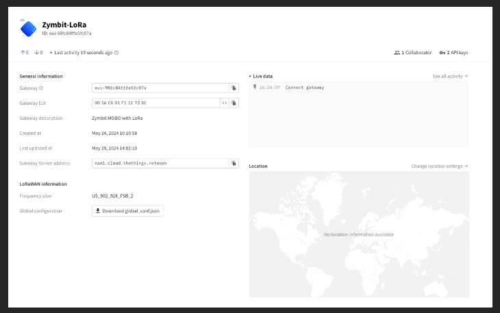
You can see that your gateway is live. Note that for some reason the GPS unit does not seem to report its location. I have filed an issue with the developer of this library about it and they are looking into it.
Install & Configure Bootware
Bootware - Secure File System Management & Recovery
Bootware is software from Zymbit that helps you configure and manage your Zymbit SEN and Raspberry Pi assets seamlessly and securely. It allows you to have A/B partitioning for reliable, recoverable updates over the air, and is simple to configure and use.
A/B updates managed in secure silicon.
Encrypted filesystem and user kernel.
Signed images and updates.
Fallback and recovery options.
Seamless integration with Raspberry Pi OS and Ubuntu.
Easy upgrade path from standard RPi products.
Available on most Zymbit products.
Installing Bootware
curl -sSf https://raw.githubusercontent.com/zymbit-applications/zb-bin/main/install.sh | sudo bash
This will install the zbcli Zymbit CLI. It will also ask you some questions. Since
zb-install.sh: bootstrapping the zbcli installer
    ---------
    Pi Module:         Raspberry Pi 4/Compute Module 4
    Operating System:  Rpi-Bullseye
    Zymbit module:     Secure Compute Module
    Kernel:            kernel8.img
    ---------

✔ 'zbcli' comes with software signing by default. Include hardware key signing? (Requires SCM or HSM6) · Yes
✔ Select version · zbcli-1.2.0-29
Installing zbcli
Installed zbcli. Run 'zbcli install' to install Bootware onto your system or 'zbcli --help' for more options.
zb-install.sh: cleaning up
Since we are installing this on an SEN, which uses a Secure Compute Module (SCM) we can use hardware signing to sign our Bootware images.
We can now use the CLI to install Bootware:
sudo zbcli install
This will trigger an install, and a reboot
zymbit@zymbit-dev:~ $ sudo zbcli install
    ---------
    Pi Module:         Raspberry Pi 4
    Operating System:  Rpi-Bullseye
    Zymbit module:     Secure Compute Module
    Kernel:            kernel8.img
    ---------
     Deleted '/boot/uboot.env'
   Installed 'u-boot-tools'
     Deleted '/usr/bin/zb_get_root_dev.sh'
       Found OpenSSL 1
✔ Found /boot/zb_config.enc. Overwrite this file? · yes
     Created '/boot/zb_config.enc'
    Modified zbconfig 'kernel_filename'
   Installed zboot
    Modified '/etc/rc.local'
    Modified '/boot/config.txt'
    Modified /etc/update-motd.d/01-zymbit-fallback-message
? A reboot into zboot is required. Reboot now? (y/n) › yes
Once the machine reboots, we will create our first zboot image from the running system:
In order to complete this step, you will need a USB Drive on which to create the image. Once you have plugged that in, make sure it is erased:
sudo fdisk -W always /dev/sda
That will ask you to create a partition table:
Welcome to fdisk (util-linux 2.38.1).
Changes will remain in memory only, until you decide to write them.
Be careful before using the write command.

Device does not contain a recognized partition table.
Created a new DOS (MBR) disklabel with disk identifier 0x27b0681a.

Command (m for help): n
Partition type
   p   primary (0 primary, 0 extended, 4 free)
   e   extended (container for logical partitions)
Select (default p): p
Partition number (1-4, default 1):
First sector (2048-125313282, default 2048):
Last sector, +/-sectors or +/-size{K,M,G,T,P} (2048-125313282, default 125313282):

Created a new partition 1 of type 'Linux' and of size 59.8 GiB.
Partition #1 contains a ext4 signature.

The signature will be removed by a write command.

Command (m for help): w
The partition table has been altered.
Calling ioctl() to re-read partition table.
Syncing disks.
The important thing to notice there is that you will enter n to create a new partition map, then p to make it a Primary partition. After that you can simply accept the defaults and then enter w to write the partition map to the disk.
Once that’s done, you’ll have to create a filesystem on the disk
sudo mkfs.ext4 -j /dev/sda1 -F
Which will create am ext4 filesystem on the disk
mke2fs 1.47.0 (5-Feb-2023)
Creating filesystem with 15663904 4k blocks and 3916304 inodes
Filesystem UUID: 4a3af5d0-bac4-4903-965f-aa6caa8532cf
Superblock backups stored on blocks:
    32768, 98304, 163840, 229376, 294912, 819200, 884736, 1605632, 2654208,
    4096000, 7962624, 11239424

Allocating group tables: done
Writing inode tables: done
Creating journal (65536 blocks): done
Writing superblocks and filesystem accounting information: done
Now you’re ready to create your boot image!
You’ll need to mount the new disk:
sudo mount /dev/sda1 /mnt
And run the imager
sudo zbcli imager
This will again ask you some questions:
   Validated bootware installation
    ---------
    Pi Module:         Raspberry Pi 4
    Operating System:  Rpi-Bullseye
    Zymbit module:     Secure Compute Module
    Kernel:            kernel8.img
    ---------
     Created '/etc/zymbit/zboot/update_artifacts/tmp'
? Enter output directory › /mnt
✔ Enter output directory · /tmp
✔ Enter image name · z-image-1
✔ Select image type · Full image of live system
✔ (Optional) enter image version · 1.0
✔ Select signing method. Note: software/hardware keys are not interchangeable. Stick with one method. · Hardware-based keys
✔ Select key · Create new hardware keys
Notice that I used the mount point for the USB Drive as our output directory. I then chose a name and version number for the image and chose to use a software key, since I’m using a Zymkey.
Don’t be surprised if this step takes a while. What it’s doing is making a complete copy of the files on the running disk, and signing it with the hardware key that it has generated.
     Created signing key
     Created '/etc/zymbit/zboot/update_artifacts/file_manifest'
     Created '/etc/zymbit/zboot/update_artifacts/file_deletions'
    Verified path unmounted '/etc/zymbit/zboot/mnt'
     Cleaned '/etc/zymbit/zboot/mnt'
     Deleted '/etc/crypttab'
    Verified disk size (required: 2.33 GiB, free: 26.39 GiB)
     Created initramfs
     Created snapshot of boot (/etc/zymbit/zboot/update_artifacts/tmp/.tmpBgEBJk/z-image-1_boot.tar)
     Created snapshot of root (/etc/zymbit/zboot/update_artifacts/tmp/.tmpBgEBJk/z-image-1_rfs.tar)
     Created '/mnt/tmp'
     Cleaned '/mnt/tmp'
     Created staging directory (/mnt/tmp/.tmpEhjNN7)
     Created '/mnt/tmp/.tmpEhjNN7/header.txt'
     Created tarball (/mnt/tmp/.tmpEhjNN7/update_artifact.tar)
     Created header signature
     Created update artifact signature
     Created file manifest signature
     Created file deletions signature
     Created '/mnt/tmp/.tmpEhjNN7/signatures'
     Created signatures (/mnt/tmp/.tmpEhjNN7/signatures)
      Copied file (/etc/zymbit/zboot/update_artifacts/file_manifest) to (/mnt/tmp/.tmpEhjNN7/file_manifest)
      Copied file (/etc/zymbit/zboot/update_artifacts/file_deletions) to (/mnt/tmp/.tmpEhjNN7/file_deletions)
     Created tarball (/mnt/z-image-1.zi)
     Created '/mnt/z-image-1_private_key.pem'
       Saved private key '/mnt/z-image-1_private_key.pem'
     Created '/mnt/z-image-1_pub_key.pem'
       Saved public key '/mnt/z-image-1_pub_key.pem'
     Cleaned '/mnt/tmp'
       Saved image '/mnt/z-image-1.zi' (2.33 GiB)
    Finished in 384.8s
In order to enable resilient updates, we will be creating A/B partitions on the disk.
Bootware encrypts the A, B, and DATA partitions. The A and B partition are locked with unique LUKS keys, meaning you cannot access the Backup partition from the Active partition. The encrypted DATA partition is accessible from either the A or B partition.
Setting up this A/B partitioning scheme is usually quite cumbersome and difficult to implement. Zymbit’s Bootware has taken that process and simplified it such that it’s a relatively easy process. So let’s go through that process now and make your Pi both secure and resilient.
Create A/B partitions
Since we’ve not previously had a backup B partition, we will create one, and we will place the current image (which we know is good, since we’re currently running it) into that partition. To do that, we will update the configuration (really create it) with the zbcli tool.
sudo zbcli update-config
Will create the config that we need.
   Validated bootware installation
    ---------
    Pi Module:         Raspberry Pi 4
    Operating System:  Rpi-Bullseye
    Zymbit module:     Secure Compute Module
    Kernel:            kernel8.img
    ---------
        Info the root file system will be re-partitioned with your chosen configuration.
This process will ask you some questions to determine how to lay out your partitions. The first is what device partition layout you would like to use. Choose the recommended option:
? Select update policy ›
❯   [RECOMMENDED] BACKUP: Applies new updates to current backup filesystem and swap to booting the new updated backup partition as the active partition now. If the new update is bad, it will rollback into the pre
     Running [========================================] 2/1 (00:00:17):                                                                                                                                             WARNING! Detected active partition (28.71GB) is larger than 14.86GB needed for two filesystems.
 Active partition won't be saved!!!
 Changing update mode to UPDATE_BOTH!!!
       Using update mode (UPDATE_BOTH)
        Data partition size currently set to: 512 MB
        Info bootware will create a shared data partition after A/B in size MB specified
Next, you can select the size of the data partition. It defaults to 512MB, but I suggest increasing that to 1024MB.
✔ Enter size of data partition in MB · 1024
       Using Data Partition Size 1024MB
  Defaulting to configured endpoint '/dev/sda1'
        Info update endpoints can be either an HTTPS URL or an external mass storage device like a USB stick.
       Found update name 'z-image-1'
       Saved update name 'z-image-1'
       Using update endpoint '/dev/sda1'
Configuration settings saved
    Finished in 42.1s
We’ve now got a system that is configured to have A/B partitioning, and to apply updates to the backup partition when they are available.
To complete the process, we will actually apply the update (which is really just a copy of the currently running system). This will trigger the re-partitioning and a reboot.
sudo zbcli update
   Validated bootware installation
    ---------
    Pi Module:         Raspberry Pi 4
    Operating System:  Rpi-Bullseye
    Zymbit module:     Secure Compute Module
    Kernel:            kernel8.img
    ---------
     Cleaned '/etc/zymbit/zboot/update_artifacts/tmp'
       Found update configs
? Proceed with current configs? These can be modified through 'zbcli update-config'
    ---------
     Update endpoint   /dev/sda1
     Update name       z-image-1
     Endpoint type     LOCAL
     Partition layout  A/B
     Update policy     UPDATE_BOTH
     ---------
     Created temporary directory (/etc/zymbit/zboot/update_artifacts/tmp/.tmpCfhm6c)
     Mounted '/dev/sda1' to '/etc/zymbit/zboot/update_artifacts/tmp/.tmpyKYgR3'
       Found image tarball (/etc/zymbit/zboot/update_artifacts/tmp/.tmpyKYgR3/z-image-1.zi)
    Unpacked '/etc/zymbit/zboot/update_artifacts/tmp/.tmpCfhm6c/update_artifact.tar'
    Unpacked '/etc/zymbit/zboot/update_artifacts/tmp/.tmpCfhm6c/signatures'
    Unpacked '/etc/zymbit/zboot/update_artifacts/tmp/.tmpCfhm6c/header.txt'
    Unpacked '/etc/zymbit/zboot/update_artifacts/tmp/.tmpCfhm6c/file_manifest'
    Unpacked '/etc/zymbit/zboot/update_artifacts/tmp/.tmpCfhm6c/file_deletions'
     Decoded header signature
     Decoded image signature
     Decoded manifest signature
     Decoded deletions signature
       Found header data
       Found image data
       Found manifest data
       Found file deletions data
    Verified header signature
    Verified image signature
    Verified manifest signature
    Verified file deletions signature
    Modified zbconfig 'public_key'
    Modified zbconfig 'new_update_needed'
    Modified zbconfig 'root_a'
    Modified zbconfig 'root_b'
    Modified zbconfig 'root_dev'
      Copied file (/boot/firmware/usr-kernel.enc) to (/boot/firmware/zboot_bkup/usr-kernel-A.enc)
      Copied file (/boot/firmware/kernel8.img) to (/boot/firmware/zboot_bkup/kernel8.img)
    Modified zbconfig 'update_with_new_image'
    Modified zbconfig 'kernel_filename'
? Scheduled update for the next reboot. Reboot now? (y/n) › yes
When it asks to reboot, say yes, and then wait.
Once your Pi is rebooted, log in and check to see that it’s correct.
lsblk
NAME              MAJ:MIN RM  SIZE RO TYPE  MOUNTPOINTS
sda                 8:0    1 59.8G  0 disk
└─sda1              8:1    1 59.8G  0 part
mmcblk0           179:0    0 29.7G  0 disk
├─mmcblk0p1       179:1    0  512M  0 part  /boot/firmware
├─mmcblk0p2       179:2    0 14.1G  0 part
│ └─cryptrfs_A    254:0    0 14.1G  0 crypt /
├─mmcblk0p3       179:3    0 14.1G  0 part
└─mmcblk0p4       179:4    0    1G  0 part
  └─cryptrfs_DATA 254:1    0 1008M  0 crypt
Notice that we now have two cryptfs devices. These are fully signed and encrypted filesystems.
What if the update had failed? Here’s the beauty of A/B partitioning with Bootware: if the system fails to boot (it fails to reach a systemd init target for 3 times in a row), Bootware will revert to the known-good partition, bringing your device back on-line.
Verifying the changes
We’ve created A/B partitions, and have verified that they are both there, and that we are booted out of the active (A) partition. As part of the Bootware initialization we just performed, the same image was also installed on the B partition. We can verify this by running
sudo zbcli rollback-swap
This will trigger a reboot of your Pi, but when you log back in, run
lsblk
Again and see what filesystems you have available now.
Additional resources
If you’d like to learn more about the various secure devices that Zymbit offers, please see the Zymbit product page.
For more in-depth information on how to set the various parts up, we have detailed documentation for everything:
General troubleshooting
Zymbit application utilities
Various conformity documents
Conclusion
At this point you should have a Zymbit Secure Edge Node Developer Kit node that can successfully connect to The Things Network and forward LoRaWAN messages it receives to the network.
You should be able to create a LoRa-enabled sensor and have that sensor send data to The Things Network via your newly configured gateway.
You may be asking yourself “what next” and I’m glad you asked! You can now use your SEN to protect local data, sign data for transmission for verification purposes, and be confident that your SEN is capable of sending (and verifying) data via The Things Network LoRaWAN network either as a primary communications channel or as a back-up channel in case the onboard LAN or WiFi connections can’t be used.
If you have further questions, or want to discuss this or any other Raspberry Pi security matter, please join our Zymbit Community.
Subscribe to my newsletter
Read articles from David G. Simmons directly inside your inbox. Subscribe to the newsletter, and don't miss out.
Written by

David G. Simmons
David G. Simmons
DevRel leader since forever, huge 💜, 🌶️🧠, dog lover, Rottweiler Rescuer, clumsy coder. Always kind, not always nice. No more Xitter, but Bluesky: https://dgs.st/bsky