A simple implementation of Deferred Rendering.
 Timethy Hyman
Introduction
Hello there! In this blog post I will be explaining what deferred rendering entails and how you can start implementing it yourself.
Since my personal project is under NDA, I will not be diving into specifics, but i will give a broad explanation on how to approach the subject in the API of your choice.
Prerequisites
To implement a deferred pipeline, I’m assuming a basic understanding of a modern graphics API such as OpenGL, Vulkan or DirectX 12. I’m also assuming some experience writing shaders using HLSL or GLSL.
If this is not the case, don’t worry. The following tutorial will still give you great insight on the idea behind a deferred renderer and is not code heavy.
What is Deferred Rendering?
A deferred pipeline is essentially the separation between rendering geometry and applying light calculations to this geometry. In a normal forward rendering pipeline, geometry is rendered to the scene and every pixel of its vertices gets shaded in the same pass. The difference is that in a deferred pipeline, the first pass, often referred to as the ‘geometry pass’ will render all objects to the screen and store scene data in the G-Buffer (more on this later). After the geometry pass, we go through the ‘light pass’. In this pass we use the data stored in the G-Buffer to shade the final pixel of objects rendered to the screen. Finally we could opt to create more passes such as light passes for different types of lighting and a transparent pass for transparent objects. I will elaborate on the reasoning behind these passes later in the article.
Why would I even bother implementing a deferred pipeline?
The downside of the forward rendered pipeline is that all pixels of the objects get shaded, even the pixels that get overlapped with other geometry. This results in a lot of wasted calculations. The deferred approach is beneficial since by using a deferred pipeline, we render all geometry of the scene to the screen, and only apply lighting calculations on the final rendered pixels. By doing this, we drastically decrease the amount of calculations needed to light the scene since the amount of pixels calculated is now fixed. In a forward pipeline, we could render 2-3 lights while maintaining 60fps, with a deferred pipeline we can render thousands of lights without dropping below 60fps. (** will add profiling information)
Benefits and detriments.
The deferred pipeline also has some downsides. Setting up a deferred rendering pipeline is harder to setup compared to the standard forward rendered brother. Deferred rendering is also only beneficial in certain cases where the the separation of the geometry pass and the light pass outweigh the overhead created by the G-Buffer. Deferred rendering shines because of its scalability with the amount of lights, but it’s not ideal when:
Rendering transparent objects
since only the final visible pixel is rendered to the screen, all other pixels are discarded.
Memory and bandwidth
The deferred pipeline uses a G-Buffer which uses a large chunk of memory and bandwidth since it holds n amount of screen size textures which need to get written to and read from constantly.
Single light or low light count
If the scene does not use a lot of lights, the overhead from creating, reading and writing to the G-Buffer will not be worth it.
Anti Aliasing
MSAA is difficult because of the G-Buffer. With MSAA, each pixel would require multiple samples from the G-Buffer attributes, drastically increasing memory usage. From aortiz: “Another major flaw is that there is no easy way to make use of hardware based anti-aliasing(AA) techniques like Multi-Sampled Anti-Aliasing (MSAA).“
Lighting Algorithms constrains
Forces you to use the same lighting algorithm for most of your scene's lighting.
Opting for a deferred pipeline is beneficial when:
Rendering a lot of lights.
Rendering high geometrically complex objects.
Post processing flexibility.
By processing geometry only once during the geometry pass, deferred rendering avoids redundant calculations for geometry that would otherwise not be visible. The light pass operates only on visible pixels, independent of scene complexity. Use cases could be when rendering open world scenes with overlapping geometry, for example a dense forest.
Post processing becomes easier because screen space data needed is already stored in the G-Buffer. This simplifies implementation of effects like SSAO ( Screen Space Ambient Occlusion ), Motion Blur and Depth of Field.
The G-Buffer.
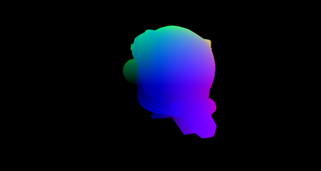
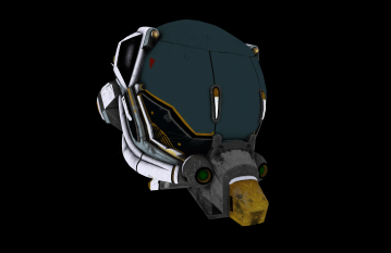
We create a G-Buffer which holds Render Targets. These Render Targets, can be written to in a pixel shader. In this shader we store attribute data in a big buffer. We need this data to do the light calculations in the light pass later on. The data stored in a G-Buffer varies from implementation to implementation, but generally it will hold the following:
Position Data
Albedo Data
Normal Data
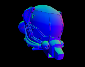
Depth Information

** When using Blinn-Pong as the shading model, the specular intensity is also stored here. (source LearnOpenGL)
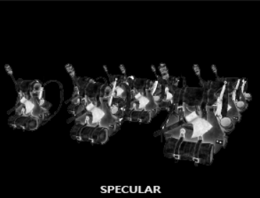
These buffers should be linked to textures so we can use them in other shaders.
Implementation.
The General Idea
To implement a deferred pipeline we need to do a few things. First of all we need to create 3 Render Targets, one for each attribute mentioned above. We need to enable writing to these Render Targets, and we need to create a separate Render Target Mask for the G-Buffer. This mask needs to get initialized with the previously created Render Targets. Finally when switching between passes, you want to set the correct Render Target to output to. More on this later.
The next step is to separate the pipeline into multiple passes. A geometry pass where we load all geometry vertices into the vertex shader and render the geometry to the scene. In the pixel shader of this pass we also fill the G-Buffer attributes. Positions get filled with the world space positions of the mesh, normals with the normals provided by the mesh ( or calculated using normal mapping ), and finally the albedo texture gets sampled and its data stored in the corresponding buffer.
The light pass.
After the geometry pass, we want to create a light pass with its own set of shaders. In this example i will on two variations of the implementation. A simple way to implement this, would be to render a quad to the screen using the vertex shader and sampling the G-Buffer in the pixel shader to do the lighting calculations. This works, and is already an improvement in regards of a forward rendered pipeline, but in this case we do no light culling. We can optimize this further. Light culling is important because of distance attenuation, where for example, the light of a lighter should not affect an object 50km away. Even if you add an attenuating function, there will always be some light contribution, even if its very minimal. Now you might ask yourself.. “What if i just add an if statement for when the light is past a certain threshold?” This would indeed solve that issue, but having an if statement in the pixel shader is expensive considering it would have to be done for every light on every pixel. Thing brings us to the topic of light culling.
Light culling is extremely important in a deferred rendering pipeline considering we intend to render a lot of lights. After some research i came to the conclusion that there are 2 good ways to do this, clustered shading and bounding volume culling. I will be covering the volume culling.
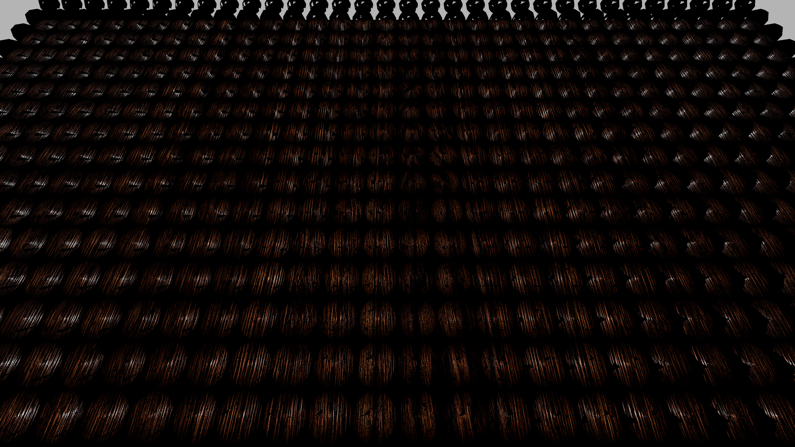
To do this we want to render spheres into the scene. By sending sphere vertex positions to the vertex shader, the pixel shader will only consider the pixels within these spheres for the lighting calculation.
The benefit of this is that now, the pixel shader will not iterate over every pixel, but only the pixels we are interested in.
In the image below, i rendered many spheres to encompass the desired geometry. Only the geometry within the grey sphere volumes get shaded. The geometry located at my mouse position does not get shaded.
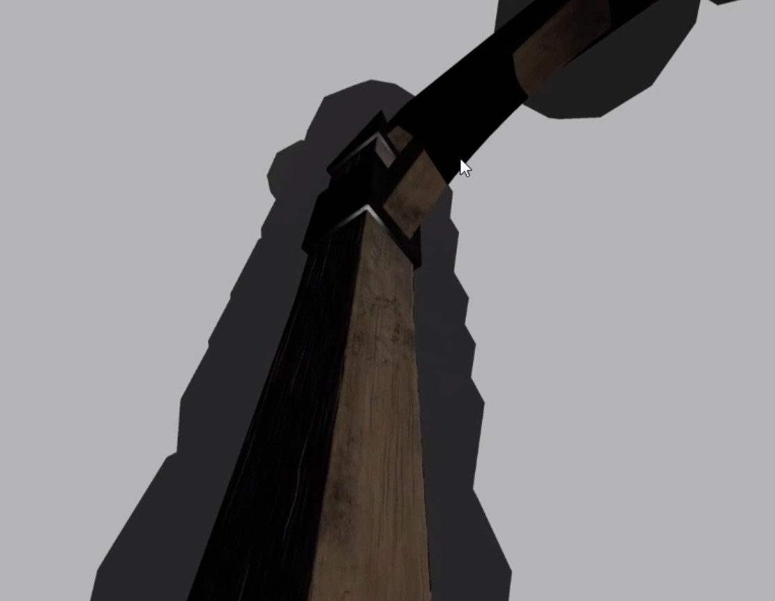
Another important note is that these spheres scale with their radius. In my example the radius is 1 so i need more lights, a smoother approach would be to make the radius bigger.
To find the UV coordinates of the affected pixels, we apply the following math formula:
    // This is a perspective divide.
    // The hardware does this divide automatically when calculating the fragment location on the screen
    float2 screenUV = input.screenPos.xy/input.screenPos.w;

    // Changes coordinate frame from [-1;1] to [0; 1]
    screenUV = (screenUV + float2(1.0)) / 2.0f;

    // Flips the vertical coordinate
    screenUV.y *= -1;
This provides us with the screen coordinates affected by the spheres. Don’t worry too much about the math behind it if you don’t understand it. If you are interested in reading more about it, i would recommend the following source.
Now we can use these UV’s to sample the G-Buffer data.
// retrieve data from G-buffer
    float3 FragPos = texture(gPosition, TexCoords).xyz;
    float3 Albedo = texture(gAlbedoSpec, TexCoords).xyz;
    float3 Normal = texture(gNormal, TexCoords).xyz;
Final Pass
In the final pass we want to render a quad to the screen and sample the data previously written to G-Buffer. This is the easiest part since it only requires us to sample the texture with all previous light calculations and output it to the screen.
float4 main(V2P input)
{
    float4 result;

    result = texture(gFinal, TexCoords);

    return result;
}
Switching between passes
First of all its important to make sure we sync the GPU before rendering anything to the screen with each pass.
Geometry pass setup: Have all G-Buffer render targets available for writing. If you don’t, the buffers left out will not be filled, resulting in undefined behavior. Also make sure that the selected Render Target Mask is the G-Buffer mask created earlier. This pass uses a simple Depth Stencil Control.
Light pass setup: When switching to the light pass its important you set the Render Target Mask to the mask created for the initial (not G-Buffer) Render Target. Additionally you want to set a designated Final G-Buffer as the Render Target to output to since the result of the pixel shader will be stored in this G-Buffer slot. Finally we need to setup the correct Depth Stencil Control. In this pass we do not want to write with depth, but it depth testing itself should be enabled.
Final pass setup: For the final pass we want to select the initial Render Target and Render Target Mask again. Here we do not use the G-Buffer. Finally for Depth Stencil Control, we want all depth testing and depth writing to be disabled. In this pass we render to a 2D quad.
Alternative passes
In my implementation i only went over the point light pass. Ideally we create a separate shader as well to handle direct lighting. We do this to avoid something called an ‘uber-shader’ which is a big shader which handles all calculations. Aortiz Alguero phrases it as follows: “And therein lies the biggest perk of deferred shading, it reduces the number of responsibilities of a shader through specialization. By dividing the work between multiple shader programs we can avoid massively branching “uber-shaders” and reduce register pressure — in other words, reduce the amount of variables a shader program needs to keep track of at a given time.”
If we want to render transparent objects we need to add another pass which handles this. As the deferred pipeline does not support this, which means these objects need to be forward rendered.
Further Optimizations
The deferred pipeline allows us to perform certain optimizations.
We can utilize light culling techniques such as clustered shading, to further optimize our renderer.
I have not implemented this myself yet, but the general idea behind this optimization is that we divide the view frustrum into 3D grids and we quickly calculate a list of lights intersecting each volume of this grid.
A beautiful article elaborating this optimization is found here.
We can reconstruct the world position of the object using the depth buffer.
The main benefit here is that the G-Buffer becomes smaller. Storing the position of each pixel directly in the G-buffer requires storing three 32-bit components (X, Y, Z). Reconstructing the positions will in turn save a lot of memory. This in turn also reduces the bandwidth required to read and write from the G-Buffer.
This would look something like this:
 float3 CalculatePosFromDepth(float screenX, float screenY, float screenZ)
{
    screenY *= -1;

    // NDC are the normalized device coordinates from -1 to 1
    float ndcX = (2.0f * screenX) - 1.0f;
    float ndcY = (2.0f * screenY) - 1.0f;
    float ndcZ = screenZ;

    float4 clipCoords = float4(ndcX, ndcY, ndcZ, 1.0f);

    // Inverse projection
    float4 viewCoords = mul(Camera->invertedProj, clipCoords);

    // Inverse view transformation
    float4 worldCoords = mul(Camera->invertedView, viewCoords);

    // Extract the world position (x, y, z)
    return worldCoords.xyz / worldCoords.w;
}
An article explaining this in more detail here.
Finally we can look into occupancy
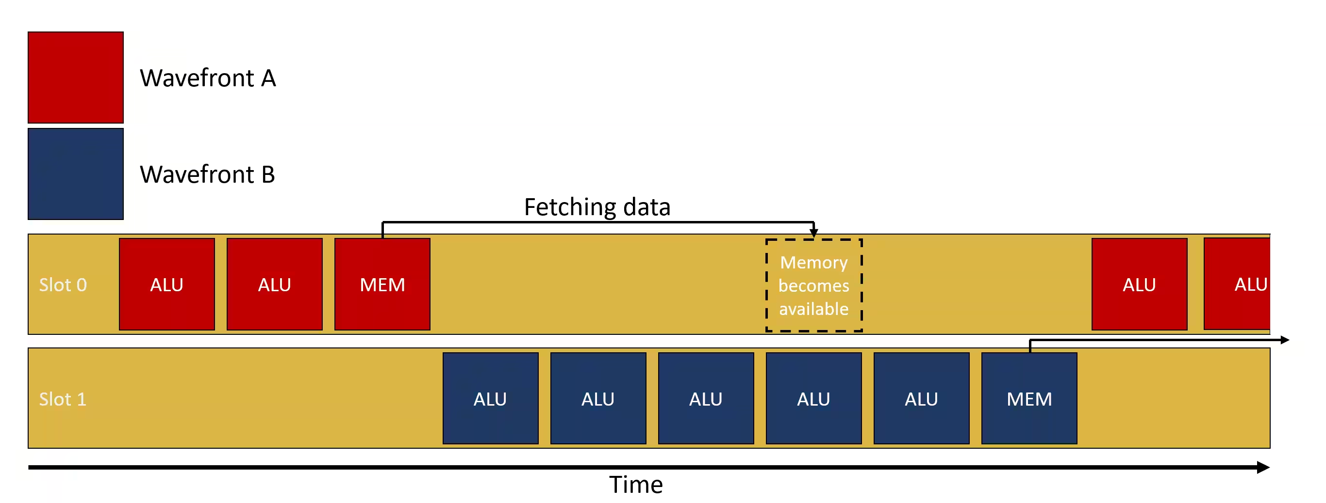
Occupancy is essentially how well the GPU can hide memory latency. The GPU will break down tasks into wavefronts and assign these wavefronts to SIMD to operate on. Multiple wavefronts can be assigned to a single SIMD, but only 1 wavefront can be executed at time. Afterwards the GPU can switch between wavefronts when one of the wavefronts is waiting for data to be loaded from memory.
Source of the image.
Ideally the SIMD is never idle. For this to happen, the SIMD should have as many wavefronts attached to it as possible. If a SIMD can hold for example 16 wavefronts, it is in a better position to hide latency when it has 16 wavefronts assigned to it (occupancy is 16/16 = 100%), than if it has only 1 wavefront assigned (occupancy of 1/16). If this 1 wavefront is waiting for data to be fetched from memory, the GPU can not switch wavefronts and do other computations while waiting.
Adittionally, occupancy is only beneficial in cases where data needs to be loaded. This means that if there are workloads where the wavefronts only do calculations without needing to look up data from memory, the workload would not benefit from increased occupancy. Higher occupancy is ideal when a workload needs to load data from memory, do computations on this data and then store it.
Finally occupancy can be limited because of a few factors. The Vector General Purpose Registers (VGPR), the Local Data Share (LDS) and the Thread Group Size.
Your GPU profiler will tell you what is limiting your occupancy.
Now that we understand what occupancy is, how do we influence it to optimize our program?
In my case for example my occupancy was limited by the VGPR’s. I was using 36 VGPR’s which causes a Tail Effect. The tail effect occurs when the total number of threads is not divisible by 32. If we have 40 threads, we would need 2 wavefronts to assign these threads. the last wavefront would only be using 8 threads. This leads to slower program execution.
To reduce the amount of VGPR’s, you want to reuse variables in the shader instead of creating new ones for intermediate calculations. You should also avoid using vectors where possible and use scalars instead. For example:
// Inefficient: Unnecessary vector size
vec4 color = vec4(1.0, 0.0, 0.0, 1.0);
vec4 PixelColor = color;

// Better: Use individual scalars
float r = 1.0;
float g = 0.0;
float b = 0.0;
float a = 1.0;
PixelColor = vec4(r, g, b, a);
This is the article where i learned about Occupancy if you want to read more in depth about it.
Conclusion.
To conclude, a deferred renderer is an amazing optimization when it comes to complex geometry or a scene with a lot of lights. It scales well with lights and does not waste cycles computing pixels that will never make it on the screen. It has it’s flaws such as constantly reading and writing to the G-Buffer, but this overhead quickly becomes worth it with the right geometrical and lighting conditions mentioned above. The deferred pipeline also makes post processing effects easier since the G-Buffer already contains most data needed, and also allows for further optimizations in for example light clustering.
That concludes the basic implementation of a deferred pipeline. I hope it was useful to you whether you are an experienced graphics programmer, someone looking for a new challenge or just a curious reader.
If you happen to have any questions or corrections, feel free to leave a comment.
Future work
In the future i intend to optimize the project more and add light clustering. Once that is implemented i will update this article with my findings on the subject as well.
Further Reading:
Deferred Shading by Joey de Vries.
Rendering Technology of Killzone 2, by Michal Valient.
A Primer On Efficient Rendering Algorithms & Clustered Shading, by Aortiz Alguero.
The 3 part Deferred Shading tutorial by OGLDev.

Subscribe to my newsletter
Read articles from Timethy Hyman directly inside your inbox. Subscribe to the newsletter, and don't miss out.
Written by

