Demystifying The OSI Model
 Tanimola Miracle
INTRODUCTION
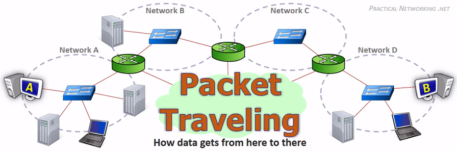
Ever wondered how your pictures or video (essentially data) travels from the internet to your screen in the blink of an eye? Or how your email magically lands in your friend’s inbox across the globe? The answer lies in a 7-layer blueprint that keeps the internet running flawlessly called the OSI Model.
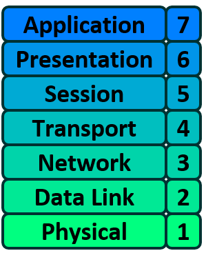
OSI Model is a set of seven independent functions which combine to accomplish the end-goal of Computer to Computer communication.
Just like a car consists of distinct components that work together to achieve the goal of moving forward. A battery powers the electronics, an alternator recharges the battery, an engine drives the crankshaft, and an axle transfers this motion to the wheels. Each part operates independently yet contributes to the overall function. As long as every component is in working order, the car continues to move forward.
The OSI model consists of seven distinct layers, each serving a specific purpose. Together, these layers work in unison to facilitate complete data communication between computers.
In this article we’ll look at these individual layers, their individual responsibility and how they perform their unique function to support the overall end goal of computer-to-computer communication.
OSI Layer 1 - THE PHYSICAL LAYER
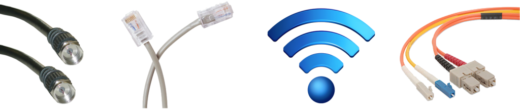
The Physical Layer is the first layer of the OSI model, and its main job is to handle the actual physical connection between devices. It deals with the transmission of raw data (bits—0s and 1s) through cables, radio waves, or any other physical medium.
This layer represents the physical medium which is carrying the traffic between two nodes. For example, Ethernet cable or Serial Cable. However, despite its name, the Physical Layer is not limited to wired connections. When the OSI model was developed in the 1970s, wireless communication was not yet widely considered, but today, Wi-Fi is also categorized under this layer, even though it lacks a tangible physical form.
In essence, Layer 1 is anything that carries 1’s and 0’s between two nodes/hosts.
Simply put, Layer 1 includes any medium responsible for transmitting raw data between two devices. The format of the data transmission depends on the medium in use:
Ethernet transmits bits as electrical signals.
Wi-Fi transfers bits through radio waves.
Fiber optics send bits as light pulses.
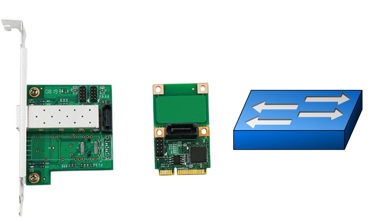
In addition to physical cables, Repeaters and Hubs also function at this layer.
A Repeater regenerates a signal from one medium to another, enabling multiple cables to be linked together, thereby extending the signal’s reach beyond the limitations of a single cable. These devices are frequently used in large Wi-Fi networks, where a single network is extended across multiple access points to provide broader coverage.
A Hub operates as a multiport Repeater. When multiple devices—say four—are connected to a Hub, any data transmitted by one device is duplicated and sent to all the others.
To learn more about repeaters and hubs check my previous article - Network Devices
Things to note about Layer 1:
It’s all about physical connections and hardware.
It deals with raw data transmission (bits, electrical signals, light pulses, radio waves).
If the Physical Layer fails, communication stops entirely because no data can be sent or received.
OSI Layer 2 - DATA LINK LAYER
The Data Link layer of the OSI model is responsible for interfacing with the Physical layer. Also, Layer 2 is responsible for putting 1’s and 0’s on the wire, and pulling 1’s and 0’s from the wire.
The Data Link Layer also acts as a bridge between the Physical Layer and higher network layers that we’ll learn about shortly. Its primary job is to manage how data is sent and received over the physical layer.
The Network Interface Card (NIC) that you plug your Ethernet wire into handles the Layer 2 functionality. It receives signals from the wire, and transmits signals on to the wire. Your WiFi NIC works the same way, receiving and transmitting radio waves which are then interpreted as a series of 1’s and 0’s. Layer 2 will then group together those 1’s and 0’s into chunks known as Frames.
There is an addressing system that exists at Layer 2 known as the Media Access Control address, or MAC address. The MAC address uniquely identifies each individual NIC. Each NIC is pre-configured with a MAC address by its manufacturer.
In addition, Switches also operate at layer 2. The main role of a switch is to manage/facilitate communication within a network.
The Data Link Layer's core function is to ensure that data packets travel from one NIC to another. In simpler terms, Layer 2 is responsible for hop-to-hop delivery, ensuring data moves smoothly between directly connected network devices.
OSI Layer 3 - Network Layer
The Network Layer is responsible for delivering data packets from one device to another, even across different networks. To achieve this, it uses a unique addressing system that can logically identify every device connected to the internet. This system is called the Internet Protocol Address popularly known as IP Address.
Unlike MAC addresses, which are permanently assigned to a device’s hardware, an IP address is considered logical because it can change. Devices can be assigned different IP addresses depending on the network they connect to, making it more flexible than the fixed MAC addresses which are burned into the NIC by the manufacturer.
Routers are network devices that operate at Layer 3 of the OSI model. Their primary role is to enable communication between different networks. Essentially, a router acts as a boundary, ensuring data is properly directed when a device needs to connect to another device outside its local network.
DATA LINK LAYER vs NETWORK LAYER
To fully grasp how data moves between computers/hosts, it's essential to differentiate between Layer 2 (Data Link Layer) and Layer 3 (Network Layer). A common question arises: If every Network Interface Card (NIC) already has a unique MAC address (Layer 2), why do we also need IP addresses (Layer 3)?
The reason is that these two addressing methods serve distinct purposes:
Layer 2 uses MAC addresses and is responsible for packet delivery from hop to hop.
Layer 3 uses IP addresses and is responsible for packet delivery from end to end.
When a computer needs to send data, it first bundles it within an IP header, which contains critical details like the source and destination IP addresses—identifying the sender and final recipient.
Next, this IP packet is further encapsulated within a MAC header, which includes the source and destination MAC addresses. The MAC addresses correspond to the devices handling the current hop in the journey, guiding the packet toward its final destination.
The following illustration will help clarify this concept:
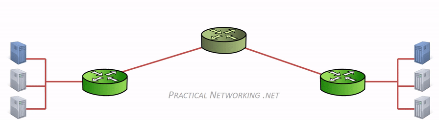
At each router along the path, the MAC address header is removed and replaced with a new one to facilitate the next hop. However, the IP header, created by the original sender, remains intact until it reaches the final destination. This demonstrates how the IP header manages end-to-end delivery, while the multiple MAC headers involved handle the hop-to-hop delivery at each stage of the journey.
OSI Layer 4 – Transport
The Transport Layer of the OSI model is responsible for identifying and managing different network data streams.
At any moment, a user's computer may be running multiple applications—browsing the internet, streaming music, and using a chat app—all of which are simultaneously sending and receiving data. Since all incoming data arrives as raw 1s and 0s through the Network Interface Card (NIC), there must be a way to determine which data belongs to which application.
This is where Layer 4 (Transport Layer) comes in, ensuring that each data stream reaches the correct application.
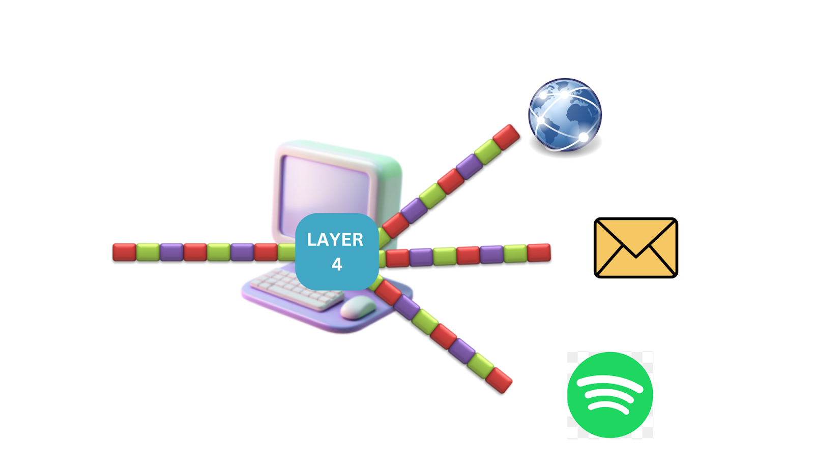
Layer 4 manages network streams using a system called Port Numbers.
There are two primary methods for distinguishing these streams:
Transmission Control Protocol (TCP)
User Datagram Protocol (UDP)
Each protocol has 65,536 port numbers, and a specific application stream is identified using a combination of Source and Destination ports, along with their Source and Destination IP addresses.
While both TCP and UDP handle data transmission differently, their internal mechanisms and differences are beyond the scope of this discussion. These topics will be explored in a future article.
Key Takeaway
Layer 2 manages hop-to-hop delivery.
Layer 3 ensures end-to-end delivery.
Layer 4 is responsible for service-to-service communication, ensuring that data reaches the correct application.
OSI Layer 5, 6 & 7
From a Network Engineering standpoint, the distinction among Layers 5, 6, and 7 is often minimal. The TCP/IP model, a widely used framework for Internet communication, consolidates these three layers into a single layer.
Many network professionals refer to these layers collectively as L5-7, L5+, or simply L7. We will adopt the same approach.
The OSI model’s Session, Presentation, and Application layers manage the final processes before the transmitted data—facilitated by Layers 1-4—is presented to the end user.
DATA WRAPPING AND UNWRAPPING
Before concluding our discussion on the OSI Model, it's important to cover encoding and decoding (encapsulation and decapsulation), the processes by which data moves through the network layers.
When sending data, it travels from the top layer to the bottom, with each layer adding necessary information to ensure proper delivery. When receiving data, the process is reversed, stripping away these added details as the data moves back up to the application layer.
Here’s a simplified breakdown of how headers are added:
Layer 4 (Transport): Adds a TCP/UDP header containing the source and destination ports.
Layer 3 (Network): Adds an IP header, which includes the source and destination IP addresses.
Layer 2 (Data Link): Adds an Ethernet header, containing the source and destination MAC addresses.
At the receiving end, each layer removes its respective header, passing the core data up the stack until it reaches the application layer.
We’ll explore a graphical example that aims to simulate how this would work to better aid our understanding.

It's essential to understand that as data travels through the network, it moves down the protocol stack, with each layer appending its own header to facilitate its function. Upon reaching the destination, these headers are removed sequentially, layer by layer, as the data ascends back to the Application layer.
CONCLUSION
The OSI model provides a structured way to understand how data moves across networks, breaking down communication into seven distinct layers, each with a specific role. From the Physical Layer (Layer 1), which handles raw data transmission, to the Application Layer (Layer 7), where users interact with network services, every layer plays a crucial part in ensuring seamless communication.
By exploring each layer, we’ve seen how data is packaged, addressed, transmitted, and managed from one device to another. Understanding the OSI model is key for anyone working with networks, whether troubleshooting connection issues or optimizing data flow. By grasping how each layer functions, you gain a deeper insight into how the internet and modern networks operate.
As technology evolves, the OSI model remains a foundational guide, helping us navigate the complexities of networking with clarity and structure.
Note: The Animated Illustration in this guide were gotten from practicalnetworking.net
Subscribe to my newsletter
Read articles from Tanimola Miracle directly inside your inbox. Subscribe to the newsletter, and don't miss out.
Written by