The internals of TCP: A deep dive
 Siddhartha S
Introduction
TCP has been the foundational protocol for numerous higher-level protocols, such as HTTP and WebSockets, due to its guarantee of data integrity. Imagine querying a database table and missing a few rows of data—that would be catastrophic. Yet, we make database calls without concern about missing data, thanks to TCP's integrity guarantees. In networking, balancing data integrity with latency is a challenge, especially given the unpredictable nature of the internet. We never know how many routers our network calls hop through, and despite many routers or switches potentially dropping packets, data loss is not an issue.
In the first article of this networking series, we briefly discussed TCP connections, examining how the OS handles them internally. We concluded with several open-ended questions. I recommend reviewing that article, as it provides an essential piece of the puzzle we aim to complete.
This article, I believe will clarify your understanding of TCP and dispel misconceptions about this enduring protocol that has stood the test of time for over the past four decades
IP Packet Header
In our previous discussion, we explored how IP packets exist at Layer 3 of the OSI model, while TCP segments operate at Layer 4. A TCP segment, along with its header, gets stuffed inside the IP Packet data and gets sent.
To fully understand the subsequent sections, it is important to familiarize ourselves with the IP packet header. Below is a diagram illustrating the IP packet header structure:
    0                   1                   2                   3
    0 1 2 3 4 5 6 7 8 9 0 1 2 3 4 5 6 7 8 9 0 1 2 3 4 5 6 7 8 9 0 1
   +-+-+-+-+-+-+-+-+-+-+-+-+-+-+-+-+-+-+-+-+-+-+-+-+-+-+-+-+-+-+-+-+
   |Version|  IHL  |Type of Service|          Total Length         |
   +-+-+-+-+-+-+-+-+-+-+-+-+-+-+-+-+-+-+-+-+-+-+-+-+-+-+-+-+-+-+-+-+
   |         Identification        |Flags|      Fragment Offset    |
   +-+-+-+-+-+-+-+-+-+-+-+-+-+-+-+-+-+-+-+-+-+-+-+-+-+-+-+-+-+-+-+-+
   |  Time to Live |    Protocol   |         Header Checksum       |
   +-+-+-+-+-+-+-+-+-+-+-+-+-+-+-+-+-+-+-+-+-+-+-+-+-+-+-+-+-+-+-+-+
   |                       Source Address                          |
   +-+-+-+-+-+-+-+-+-+-+-+-+-+-+-+-+-+-+-+-+-+-+-+-+-+-+-+-+-+-+-+-+
   |                    Destination Address                        |
   +-+-+-+-+-+-+-+-+-+-+-+-+-+-+-+-+-+-+-+-+-+-+-+-+-+-+-+-+-+-+-+-+
   |                    Options                    |    Padding    |
   +-+-+-+-+-+-+-+-+-+-+-+-+-+-+-+-+-+-+-+-+-+-+-+-+-+-+-+-+-+-+-+-+
Source: RFC 791
Version: Specifies the IP protocol version, either IPv4 or IPv6.
IHL (Internet Header Length): Indicates the length of the header, including any options.
Type of Service: Defines aspects like priority and quality of service.
Total Length: Specifies the packet's total length, including the header and data.
Identification, Flags, Fragment Offset: These fields are used for packet fragmentation and reassembly if needed.
Time to Live (TTL): Limits the lifespan of a packet by defining the maximum number of hops it can make before being discarded. Each router decrements this value by one.
Protocol: Specifies the protocol used in the data portion (e.g., ICMP, TCP, UDP).
Header Checksum: Used to verify the integrity of the header data in IPv4 packets.
Source and Destination IP Address: Specifies the sender's and receiver's IP addresses. At Layer 3, only these IP addresses are involved in routing.
Understanding these fields will aid in navigating the complexities of network packet handling in further discussions.
TCP Connection
The Transmission Control Protocol (TCP) focuses on controlling data transmission, unlike the more lenient UDP. TCP is methodical about initiating, maintaining, and terminating data transmission. A crucial aspect is the TCP connection.
A TCP connection is bidirectional, enabling protocols like HTTP and WebSocket to operate effectively. It is initiated by the client and accepted by the server. A client is typically an application used directly by the user to initiate operations, while a server is a continuously available application that handles client requests.
Therefore, it's more practical for clients to identify the server rather than vice versa, aligning with software architecture, not any inherent TCP directionality.
TCP, a Layer 4 protocol with port visibility (see the first article), requires an established connection for data transmission. A TCP connection resembles an agreement between a client and server, identified by:
Client IP
Client Port
Destination IP
Destination Port
Establishing a TCP connection involves a three-way handshake: SYN, SYN-ACK, and ACK. TCP segments are sequenced and acknowledged. A delay in segment acknowledgment triggers a retransmission, which we will explore shortly.
Multiple connections can exist between the same client and server, with TCP segments multiplexed into a single stream. This stream is then demultiplexed and routed to the appropriate programs listening on relevant ports.
Connection Establishing
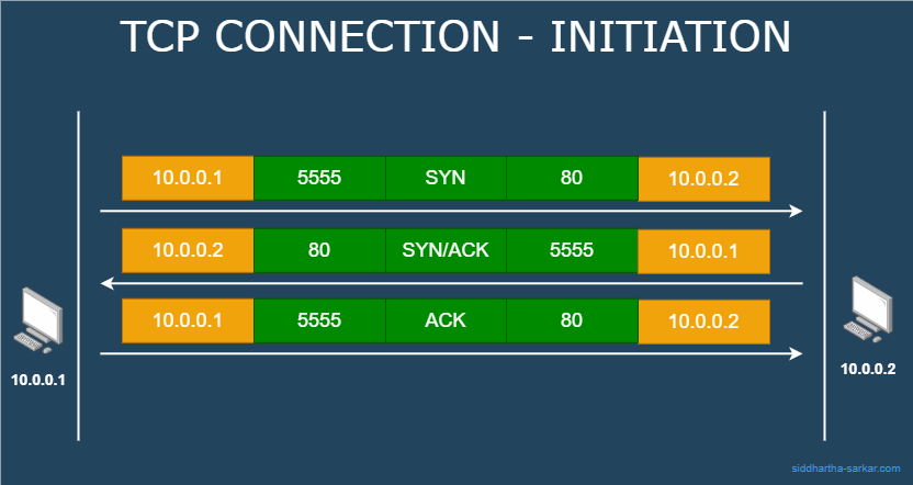
TCP connection establishment consists of three way handshake:
The sender sends a SYN request.
The receiver responds with a SYN/ACK message.
The initiator sends back an ACK message, finalizing the connection. Both sender and receiver now have sockets and file descriptors, signifying an established connection.
Transmission of Data
With the connection established, the sender begins transmitting TCP segments. These segments are acknowledged by the receiver upon receipt.

The receiver may acknowledge multiple segments with a single acknowledgment. For instance, in the given scenario (refer the diagram above), the sender might send three segments numbered based on the initial SYN connection request sequence. The receiver acknowledges the last segment, implicitly acknowledging prior segments as well.
Re transmission of Data

For illustration:
The segment with the third sequence number is dropped.
The sender waits for acknowledgement and receives acknowledgment only for sequence 2.
After a timeout, the sender retransmits the segment marked with sequence 3.
The receiver then acknowledges sequence 3.
You might be thinking what would happen if sequence 2 got dropped while sequence 3 went through. Well that would result in Line of Head blocking and we will explore that in the last section of the article.
Connection Closure and connection States

While a TCP connection is established via a three-way handshake, closing it involves a four-way handshake. The connection state transitions as follows:
The sender initiates closure by sending a FIN request, entering the FIN WAIT state.
The receiver receives the FIN, sends back an ACK, and moves to the CLOSE WAIT state.
The sender receives the ACK, moving to the FIN WAIT 2 state.
The receiver enters the LAST ACK state, sending a FIN back.
The sender, on receiving the FIN, moves to the TIME WAIT state, sending a final ACK.
On receiving the last ACK, the receiver transitions the connection to the CLOSED state and waits (usually around 4 minutes) to ensure no more messages are incoming before finally moving to the CLOSED state.
The responsibility for waiting and closing the connection falls on the initiator, hence the recommendation for the client to initiate the connection. Additionally, the removal of sockets and file descriptors continues even after the connection is closed, as the OS independently manages resource disposal.
Anatomy of TCP Segment
The TCP header format is as follows:
Note: Each tick mark represents one bit position.
0                   1                   2                   3
0 1 2 3 4 5 6 7 8 9 0 1 2 3 4 5 6 7 8 9 0 1 2 3 4 5 6 7 8 9 0 1
+-+-+-+-+-+-+-+-+-+-+-+-+-+-+-+-+-+-+-+-+-+-+-+-+-+-+-+-+-+-+-+-+
|          Source Port          |       Destination Port        |
+-+-+-+-+-+-+-+-+-+-+-+-+-+-+-+-+-+-+-+-+-+-+-+-+-+-+-+-+-+-+-+-+
|                        Sequence Number                        |
+-+-+-+-+-+-+-+-+-+-+-+-+-+-+-+-+-+-+-+-+-+-+-+-+-+-+-+-+-+-+-+-+
|                    Acknowledgment Number                      |
+-+-+-+-+-+-+-+-+-+-+-+-+-+-+-+-+-+-+-+-+-+-+-+-+-+-+-+-+-+-+-+-+
|  Data |           |U|A|P|R|S|F|                               |
| Offset| Reserved  |R|C|S|S|Y|I|            Window  Size       |
|       |           |G|K|H|T|N|N|                               |
+-+-+-+-+-+-+-+-+-+-+-+-+-+-+-+-+-+-+-+-+-+-+-+-+-+-+-+-+-+-+-+-+
|           Checksum            |         Urgent Pointer        |
+-+-+-+-+-+-+-+-+-+-+-+-+-+-+-+-+-+-+-+-+-+-+-+-+-+-+-+-+-+-+-+-+
|                    Options                    |    Padding    |
+-+-+-+-+-+-+-+-+-+-+-+-+-+-+-+-+-+-+-+-+-+-+-+-+-+-+-+-+-+-+-+-+
|                             Data                              |
+-+-+-+-+-+-+-+-+-+-+-+-+-+-+-+-+-+-+-+-+-+-+-+-+-+-+-+-+-+-+-+-+
Source: RFC 793
The header consists of 5 × 4 = 20 bytes. Additional headers may be included as options. The Source Port and Destination Port fields specify the ports for the source and destination (the IP addresses are contained in the IP packet header).
The Acknowledgment Number is only relevant if the ACK flag is set. The Window Size field indicates the amount of data the receiver can handle (more on this in the Sliding Window section).
Notable are the 9-bit flags:
FIN: Indicates a connection closure request.
SYN: Initiates a sequence number for the initial handshake.
RST: Resets the connection.
ACK: Acknowledges received data.
URG: Marks urgent data.
ECE: Signals congestion notification.
CWR: Indicates congestion window reduction.
NA: Notification anomalies.
The relevance of these flags will become clearer as we explore more aspects of TCP.
Flow Control

Consider a scenario where the sender wants to transmit Segments 1, 2, and 3 to the receiver. Receiving a single acknowledgment for multiple segments is more efficient. However, the sender must have a way to know how many segments to send before waiting for an acknowledgment. Sending too many segments could overwhelm the receiver's buffer, leading to dropped segments.
This is where the Window Size field (refer to TCP segment anatomy) comes into play. Each acknowledgment from the receiver includes the current Window Size, informing the sender of how many packets can be sent.
Receiver (Sliding) Window

The sliding window is a critical mechanism in TCP used by the sender. As illustrated, assume the sender wants to transmit six segments to the receiver.
The sender transmits Segments 1, 2, and 3.
The receiver acknowledges Segment 2.
The sender realizes Segment 3 is either still in transit or lost.
The window slides to include Segments 4 and 5, keeping Segment 3 within the window.
Segments 1 and 2 are excluded from the sender's window as they have moved out of the window and may be dropped.
The sender transmits Segments 4 and 5.
Upon receiving acknowledgment for Segment 3, the window slides further to include Segment 6 and remove Segment 3.
This sliding window mechanism ensures orderly data transmission and efficient use of network resources.
But what should be the size of this window?
Clearly, the number of segments that are to be sent to the receiver are to be included in the window. The Size of the window gets set with every acknowledgement that comes back (remember the Window Size field in the TCP header?).
Congestion Control
The flow of data from sender to receiver in TCP is not solely managed by flow control. Although flow control ensures that the receiver is not overwhelmed, the data must traverse several intermediary devices such as routers and switches. These network elements might not support rapid data flow even if the receiver can handle it. Therefore, TCP also incorporates congestion control to manage data transmission effectively.
In addition to the Receiver Window (RWND), TCP utilizes a Congestion Window (CWND), which plays a crucial role in congestion control. It’s important to note that the CWND can never exceed the RWND.
There are two primary algorithms for determining the size of the CWND:
TCP Slow Start: This algorithm gradually increases the CWND size to identify the network's capacity without causing congestion.
Congestion Avoidance: This algorithm aims to optimize data flow by adjusting the CWND size to avoid congestion once the initial network capacity has been identified.
Let's explore each of these algorithms in detail.
TCP Slow Start
Ironically, despite its name, TCP Slow Start is actually the fastest among the congestion control algorithms.

In the example illustrated above:
The Congestion Window (CWND) begins with a capacity of 1 segment. Accordingly, only one segment is sent initially.
Upon receiving acknowledgment from the receiver, the CWND is increased by 1.
The sender then transmits two segments: Segments 2 and 3.
In response, the receiver sends back acknowledgments for both segments (2 and 3). As a result, the CWND increases by 2 (1 for each acknowledgment received).
With the CWND now allowing for larger transmission, the sender proceeds to send Segments 4, 5, 6, and 7.
Congestion Avoidance
Congestion Avoidance algorithm also increases the CWND but at a slower rate than TCP Slow start.

In the above diagram example:
The Congestion Window (CWND) begins with the capacity for 1 segment, so only one segment is initially sent.
Upon receiving an acknowledgment from the receiver, the CWND is increased by 1.
The sender then transmits two segments: Segments 2 and 3.
The receiver sends back acknowledgments for both segments. The CWND is increased by 1 for this entire round trip, as it pertains to the single window of data sent.
With the updated CWND, the sender now sends Segments 4, 5, and 6.
Congestion Notification
Routers operate at Layer 3 of the OSI model, providing them visibility into IP packets. IP packets include a field known as ECN (Explicit Congestion Notification). When routers detect their buffers are becoming full, they mark the ECN field in the IP packets and forward them to the receiver. Upon receiving these packets, the receiver notes the ECN marking in the IP headers and communicates this information back to the sender. The sender will reduce the transmission rate to alleviate congestion.
Nagle’s Algorithm
Nagle’s algorithm specifies that if there are in-flight segments—meaning segments that have been sent but for which an acknowledgment (ACK) has not yet been received—an IP packet will only be transmitted if it is completely filled. Conversely, if there are no in-flight segments, a packet will be sent even if it is only partially filled.

In the diagram example provided:
Three completely filled IP packets are sent, while a partially filled packet is held back.
Once the acknowledgments for the three packets are received, the partially filled packet is then transmitted.
Nagle’s algorithm is often disabled in modern networking practices because it can introduce additional latency.
Delayed Acknowledgement Algorithm
The Delayed Acknowledgment Algorithm is implemented on the receiver's side. This algorithm suggests that the receiver should wait to receive multiple packets before sending an acknowledgment (ACK). By doing so, the number of acknowledgments sent is reduced, which can help decrease overall latency in the communication process.

A problem arises when both Nagle’s algorithm and the Delayed Acknowledgment Algorithm are used simultaneously. Nagle’s algorithm, which operates on the sender's side, holds back a packet until an acknowledgment (ACK) for previously sent segments is received. Meanwhile, the Delayed Acknowledgment Algorithm, implemented on the receiver's side, waits to receive multiple segments before sending back an ACK.
This combination can create a deadlock-like situation, where the sender is waiting for an ACK that is not being sent because the receiver is holding off until it receives additional segments. As a result, this can lead to retransmissions and timeouts, negatively impacting network performance.
TCP Head of Line blocking
TCP ensures that segments are delivered in the order they are sent. Line of Head Blocking occurs when a segment in the middle of a sequence gets dropped, which particularly impacts HTTP requests because they often use the same connection to send multiple requests.

Consider the diagram example illustrated above:
Request 1 is divided into Segments 1 and 2.
Request 2 is divided into Segments 3 and 4.
If Segments 2, 3, and 4 are successfully transmitted but Segment 1 is dropped, the server will not send acknowledgments (ACKs) for Segments 2, 3, and 4 until Segment 1 is retransmitted.
As a result, Request 2 suffers delays even though it was fully transmitted, because it is dependent on the status of Request 1.
This scenario exemplifies Line of Head Blocking, where the processing of one request is held up due to the loss of an earlier packet.
Conclusion
In this comprehensive article, we built upon the foundation established in a previous piece and delved into the internals of TCP communication. We began by examining the anatomy of IP packets and then explored the mechanisms involved in TCP connection creation and closure.
We discussed various mechanisms, such as Flow Control and Congestion Control, that TCP employs to ensure smooth and reliable data transmission. The sliding window technique facilitates controlled data flow, allowing for efficient management of both flow and congestion.
Additionally, we reviewed Nagle’s algorithm and the Delayed Acknowledgment Algorithm, both designed to reduce transmissions for improved efficiency. However, we noted that their combined use can lead to counterproductive outcomes. Finally, we addressed the concept of Line of Head Blocking, illustrating its impact on data transmission.
I trust that this article has contributed to your understanding and provided valuable insights into the intricacies of TCP internals.
Subscribe to my newsletter
Read articles from Siddhartha S directly inside your inbox. Subscribe to the newsletter, and don't miss out.
Written by
Siddhartha S
Siddhartha S
With over 18 years of experience in IT, I specialize in designing and building powerful, scalable solutions using a wide range of technologies like JavaScript, .NET, C#, React, Next.js, Golang, AWS, Networking, Databases, DevOps, Kubernetes, and Docker. My career has taken me through various industries, including Manufacturing and Media, but for the last 10 years, I’ve focused on delivering cutting-edge solutions in the Finance sector. As an application architect, I combine cloud expertise with a deep understanding of systems to create solutions that are not only built for today but prepared for tomorrow. My diverse technical background allows me to connect development and infrastructure seamlessly, ensuring businesses can innovate and scale effectively. I’m passionate about creating architectures that are secure, resilient, and efficient—solutions that help businesses turn ideas into reality while staying future-ready.