Frustum Culling
 Platwo
Visual Demo
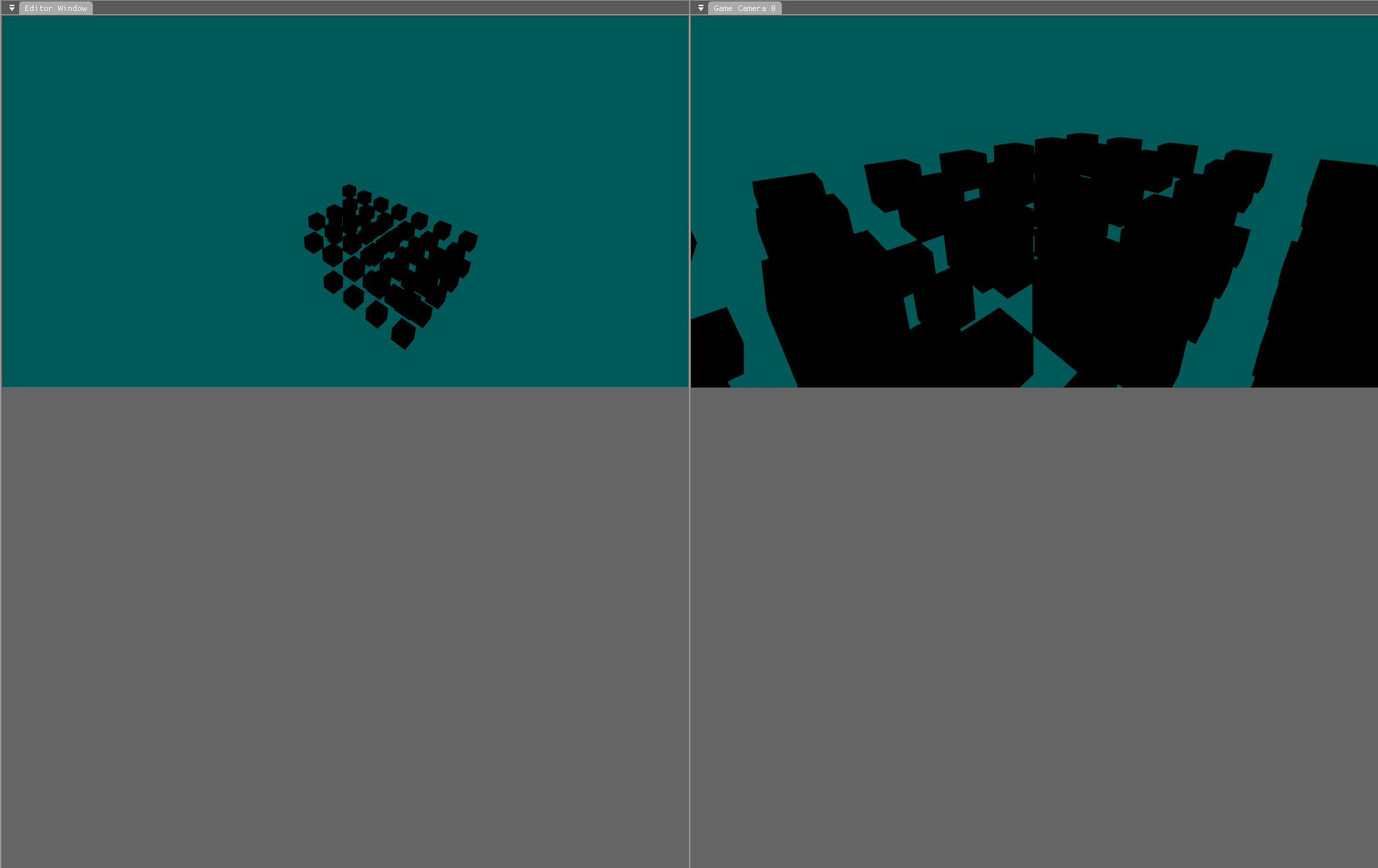
As this post is very long, it makes more sense for the visual demo to be here instead of at the end:
The video shows the result of frustum culling being applied to the scene, so that only the models that are on-screen are being passed to the GPU for rendering.
Intro
In programming there is the idea that the cheapest code to process is simply no code at all. This idea expands into the area of optimization and performance very easily, implying that the less things that a program has to process, the better it will perform. This then expands even further into the concept of culling elements from a scene. And in the case of this blog post, frustum culling.
Culling from a rendering perspective is the process of removing unneeded elements from a scene, in a way that the final scene render is the same as it was with the unneeded elements included. There are a bunch of ways to cull a virtual scene - such as occlusion culling - but the one that is going to be explained in this post is called Frustum Culling.
The Viewing Frustum
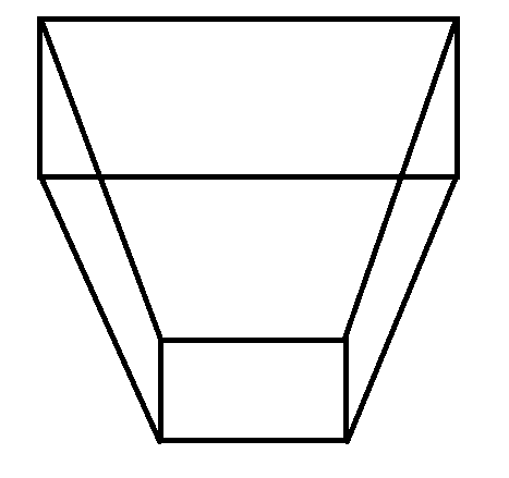
A view frustum is the name given to the bounding area that a camera can see. It looks like the image below:

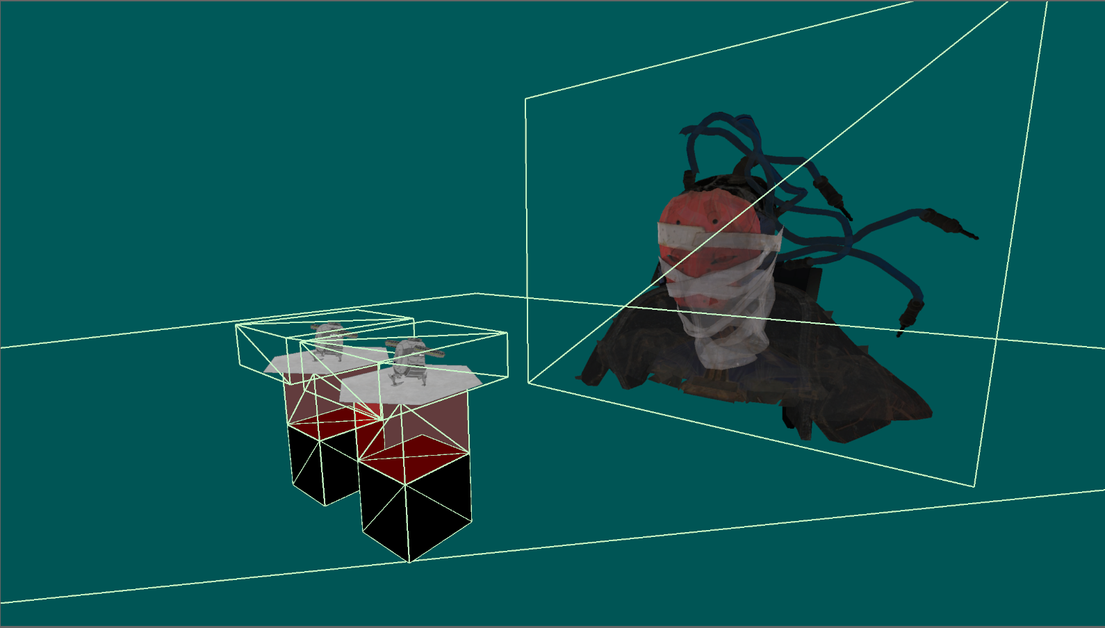
Where the camera is near the bottom centre of the image, and it is looking upwards towards the top. Everything outside of this volume cannot be seen by the camera - this is where frustum culling comes into play. If you have a heavily populated world around the camera, then some of that world will not be within the frustum, and therefore cannot be seen. Running the rendering commands for those objects anyway would be a waste of processing and performance. So, what is commonly performed here is having bounding volumes wrapped around each object, and then checking them against the frustum’s volume. If there is no overlap then the object does not need to be rendered - simple :D
In practice this is not quite so simple, especially when taking multiple camera views into account. The section below covers the maths behind this process, and the section after it covers the code behind the engine’s implementation.
Maths Concepts
Planes
In mathematics there is an equation used to define a plane:
$$Ax+By+Cz+D=0$$
$$(A,B,C)=Normal$$
$$(x,y,z)=point$$
What this equation means is that for every point passed in (x,y,z), after mapping it to the plane, if the result of the equation is zero then the point lies on the plane. If it is not zero then the sign (+ or -) of the result states which side of the plane the point is on. And the magnitude of the result is how far away the point is from the plane.
To break that information down some more, here is an example. Say you have a plane that lays across the X-Z axis. This would look like a completely flat floor stretching off in every direction. The normal of that plane could be defined as being (0, 1, 0), as the Y axis is perpendicular to the other two axis. Now if you wanted to know how far from the plane that the point (3, 2, 1) is, then you could pass in the position into the plane equation. This would become:
$$(0 * 3) + (1 * 2) + (0 * 1) + D = ?$$
Now the question becomes, what is D?
To calculate D, you need to pass in a point that you know lies on the plane. So in this case the point (0, 0, 0) would work, as the plane passes through the origin. Passing (0, 0, 0) into the plane equation gives a D value of 0. Passing this into the maths we were doing before, it becomes:
$$(0) + (2) + (0) + 0 = 2$$
Which means that the point (3, 2, 1) is two units away from the plane in the direction that the plane is facing.
Making a Frustum Out of Planes
The view area of a camera is built out of six distinct planes:
Near
Far
Top
Bottom
Left
Right
If you have a mathematical plane defined for each of the above then you can determine if a point is within the volume defined by a frustum. How this is done is through having all the planes either pointing inwards or outwards (outwards makes more sense in my opinion). Then, if a point is on the same side (for example, the negative side) of all of the planes, then it is within the volume.
This logic can then be expanded into the eight vertices that make up an axis aligned bounding box. And then, if none of the vertices are within the volume, then whatever is within the bounding box cannot be seen. How axis-aligned bounding boxes work is outlined in the next section.
AABB
Axis aligned bounding boxes (AABB) are bounding boxes that align exactly to the axis that they are defined within. Or in other words, they have no rotations. They are very useful for doing fast collision checks due to the simple maths involved in determining if a point falls inside or outside of the box.
There are numerous ways of defining an AABB that range from:
Storing all eight vertices
Storing a centre point and half extents
Storing a centre point and the half dimensions in the positive and negative directions.
Storing a min and a max position
All of these representations have their own unique benefits and drawbacks. But in this specific case, the version that is most beneficial is going to be storing min and max positions. The reason behind this is as part of the GLTF specification it enforces that the min and max values of a set of position data be stored alongside the data itself. So the code already knows the min and max values without any processing.
Engine Implementation
Converting the logic defined above into code is simple in some places, and more complex in others. For example, creating a frustum out of planes is fairly easy, but accounting for multiple cameras viewing the same scene is fairly complex.
Camera Frustum
Representing a camera’s frustum in code is not particularly difficult, but it does take a fair bit of code. Below is a trimmed down version of my frustum class definition.
class Frustum final
{
public:
    Frustum(const Maths::Vector::Vector3D<float> cameraPosition, const float nearDistance, const float farDistance, const float aspectRatio, const float FOV_Radians, const Maths::Vector::Vector3D<float>& forwards, const Maths::Vector::Vector3D<float>& up);
    Frustum(const Maths::Vector::Vector3D<float>& FrontBottomLeft, ...);

    // Plane getters
    const Collision::Plane& GetLeftPlane() const { return mPlanes[0]; }
    ...

    // Point getters
    const Maths::Vector::Vector3D<float>& GetFrontBottomLeftPoint() const { return mPoints[0]; }
    ...

    bool AABBIsWithin(const Collision::MinMaxAABB& aabb);
    bool SphereIsWithin(const Collision::Sphere& sphere);

    void UpdateInternalData(const Maths::Vector::Vector3D<float> cameraPosition, const float nearDistance, const float farDistance, const float aspectRatio, const float FOV_Radians, const Maths::Vector::Vector3D<float>& forwards, const Maths::Vector::Vector3D<float>& up);

private:
    // Planes order
    // Left side,
    // Right side,
    // Top
    // Bottom
    // Near
    // Far
    Collision::Plane mPlanes[6];

    // Points order
    // Front:
    //     - bottom left
    //     - bottom right
    //     - top left
    //       - top right
    // Back:
    //     - bottom left
    //     - bottom right
    //     - top left
    //       - top right
    Maths::Vector::Vector3D<float> mPoints[8];
};
As you can see, it is essentially just a wrapper around eight vertices, and six planes (the planes are generated from the vertices, so there will be no desync between the two).
Calculating Planes
The following code is how the engine determines the frustum’s planes from the eight points it has just calculated from the camera’s internal data.
So the flow that is happening is:
Internal camera data is passed into the frustum (data such as position, near/far distance, FOV, aspect ratio, etc)
The eight positions at the extremes of the frustum are calculated
Using the eight positions, the six planes are calculated
The code calculates the planes with them facing away from the volume, which makes the negative side being within the volume.
void Frustum::CalculatePlanesFromPoints()
{
    const Maths::Vector::Vector3D<float>& FrontBottomLeft  = mPoints[0];
    const Maths::Vector::Vector3D<float>& FrontBottomRight = mPoints[1];
    const Maths::Vector::Vector3D<float>& FrontTopLeft     = mPoints[2];
    const Maths::Vector::Vector3D<float>& FrontTopRight    = mPoints[3];

    const Maths::Vector::Vector3D<float>& BackBottomLeft  = mPoints[4];
    const Maths::Vector::Vector3D<float>& BackBottomRight = mPoints[5];
    const Maths::Vector::Vector3D<float>& BackTopLeft     = mPoints[6];
    const Maths::Vector::Vector3D<float>& BackTopRight    = mPoints[7];

    // Far plane (5) //
    mPlanes[5].mNormal = (BackTopRight - BackTopLeft).Cross(BackBottomRight - BackTopRight);
    mPlanes[5].mNormal.Normalise();
    mPlanes[5].mD = -mPlanes[5].mNormal.Dot(BackTopLeft);

    // Near plane (4) //
    mPlanes[4].mNormal = (FrontTopRight - FrontTopLeft).Cross(FrontTopRight - FrontBottomRight);
    mPlanes[4].mNormal.Normalise();
    mPlanes[4].mD = -mPlanes[4].mNormal.Dot(FrontTopLeft);

    // Left plane (0) //
    mPlanes[0].mNormal = (FrontTopLeft - BackTopLeft).Cross(BackTopLeft - BackBottomLeft);
    mPlanes[0].mNormal.Normalise();
    mPlanes[0].mD = -mPlanes[0].mNormal.Dot(BackTopLeft);

    // Right plane (1) //
    mPlanes[1].mNormal = (FrontTopRight - BackTopRight).Cross(BackBottomRight - BackTopRight);
    mPlanes[1].mNormal.Normalise();
    mPlanes[1].mD = -mPlanes[1].mNormal.Dot(BackTopRight);

    // Top plane (2) //
    mPlanes[2].mNormal = (FrontTopRight - BackTopRight).Cross(BackTopRight - BackTopLeft);
    mPlanes[2].mNormal.Normalise();
    mPlanes[2].mD = -mPlanes[2].mNormal.Dot(BackTopRight);

    // Bottom plane (3) //
    mPlanes[3].mNormal = (BackBottomRight - FrontBottomRight).Cross(BackBottomRight - BackBottomLeft);
    mPlanes[3].mNormal.Normalise();
    mPlanes[3].mD = -mPlanes[3].mNormal.Dot(BackBottomRight);
}
Plane calculations
Calculating Points
This section is here for the sake of completeness. In the part above it was mentioned that the points are calculated before the planes, which is true, but I felt that showing the plane code first made more sense. Here is the code that the engine uses to calculate the extents of the frustum:
void Frustum::CalculatePlanesFromCameraData_Perspective(const Maths::Vector::Vector3D<float>& cameraPosition, const float nearDistance, const float farDistance, const float FOV_Radians, const float aspectRatio, const Maths::Vector::Vector3D<float>& forwardsDirection, const Maths::Vector::Vector3D<float>& up)
{
    const float halfFOV = FOV_Radians / 2.0f;

    // Project the forwards vector to the centre of the near and far planes
    const Maths::Vector::Vector3D<float> centreOfFarPlane  = cameraPosition + (forwardsDirection * farDistance);
    const Maths::Vector::Vector3D<float> centreOfNearPlane = cameraPosition + (forwardsDirection * nearDistance * 2.0f);

    // Calculate the distance from the centre of the far plane to the right edge of the plane
    const float halfHeightOfNearPlane = tan(halfFOV) * nearDistance * 2.0f;
    const float halfHeightOfFarPlane  = tan(halfFOV) * farDistance;

    const float halfWidthOfNearPlane = halfHeightOfNearPlane * aspectRatio;
    const float halfWidthOfFarPlane  = halfHeightOfFarPlane  * aspectRatio;

    // Now calculate the points
    const Maths::Vector::Vector3D<float> right = forwardsDirection.Cross(up).Normalised();

    mPoints[0] = centreOfNearPlane - (right * halfWidthOfNearPlane) - (up * halfHeightOfNearPlane);
    mPoints[1] = centreOfNearPlane + (right * halfWidthOfNearPlane) - (up * halfHeightOfNearPlane);
    mPoints[2] = centreOfNearPlane - (right * halfWidthOfNearPlane) + (up * halfHeightOfNearPlane);
    mPoints[3] = centreOfNearPlane + (right * halfWidthOfNearPlane) + (up * halfHeightOfNearPlane);

    mPoints[4] = centreOfFarPlane - (right * halfWidthOfFarPlane) - (up * halfHeightOfFarPlane);
    mPoints[5] = centreOfFarPlane + (right * halfWidthOfFarPlane) - (up * halfHeightOfFarPlane);
    mPoints[6] = centreOfFarPlane - (right * halfWidthOfFarPlane) + (up * halfHeightOfFarPlane);
    mPoints[7] = centreOfFarPlane + (right * halfWidthOfFarPlane) + (up * halfHeightOfFarPlane);

    CalculatePlanesFromPoints();
}
AABB
As explained in the maths section for AABBs, there are multiple ways of representing AABBs in code. The version that has been decided to be used to represent geometry bounding areas is the min/max position storing approach, as defined in the code below:
struct MinMaxAABB
{
    MinMaxAABB()
        : mMin(-0.5f, -0.5f, -0.5f)
        , mMax(0.5f, 0.5f, 0.5f)
    {}

    MinMaxAABB(const AABB& aabb)
        : mMin(aabb.mCentre - aabb.mHalfExtents)
        , mMax(aabb.mCentre + aabb.mHalfExtents)
    {}

    MinMaxAABB(Vector::Vector3D<float> min, Vector::Vector3D<float> max)
        : mMin(min)
        , mMax(max)
    {}

    Vector::Vector3D<float> mMin;
    Vector::Vector3D<float> mMax;
};
The benefit of this approach is that it ties nicely into the extraction of data from vertex buffers. And, as each model will be locally based around its own origin anyway, the values are not going to scale too large. So, in a way, it is the same as storing the positive and negative half extents, where the entities transform position is the centre.

Visibility Checks
The vital part of the code implementation is being able to determine if a bounding area (in this case either an AABB or sphere) is at least partially within a frustum. To determine this the frustum class has the following two functions:
bool AABBIsWithin(const Collision::MinMaxAABB& aabb);
bool SphereIsWithin(const Collision::Sphere& sphere);
The logic behind each of these is fairly similar, with true being returned on any part of the bounding volume being within the frustum.
Here is the AABB - frustum collision checking code:
bool Frustum::AABBIsWithin(const Collision::MinMaxAABB& aabb)
{
    // Calculate the 8 points
    Maths::Vector::Vector3D<float> centre      = (aabb.mMin + aabb.mMax) / 2.0f;
    Maths::Vector::Vector3D<float> halfExtents = aabb.mMax - centre;

    Maths::Vector::Vector3D<float> verticies[8] = { aabb.mMin,
                                                    centre + Maths::Vector::Vector3D<float>{  halfExtents.x,  halfExtents.y, -halfExtents.z },
                                                    centre + Maths::Vector::Vector3D<float>{  halfExtents.x, -halfExtents.y,  halfExtents.z },
                                                    centre + Maths::Vector::Vector3D<float>{ -halfExtents.x,  halfExtents.y,  halfExtents.z },
                                                    centre + Maths::Vector::Vector3D<float>{ -halfExtents.x, -halfExtents.y,  halfExtents.z },
                                                    centre + Maths::Vector::Vector3D<float>{  halfExtents.x, -halfExtents.y, -halfExtents.z },
                                                    centre + Maths::Vector::Vector3D<float>{ -halfExtents.x,  halfExtents.y, -halfExtents.z },
                                                    aabb.mMax
                                                  };

    // Go through each plane and determine the AABB is fully outside any plane
    for (unsigned int i = 0; i < 6; i++)
    {
        const Collision::Plane& planeToTest = mPlanes[i];

        // Run the plane equation on each point
        // Each plane is facing outwards so we are checking to see if every point in the aabb is on the outside of a plane
        // If so then the aabb cannot be within/colliding with the frustum
        if (verticies[0].Dot(planeToTest.mNormal) + planeToTest.mD > 0.0f &&
            verticies[1].Dot(planeToTest.mNormal) + planeToTest.mD > 0.0f &&
            verticies[2].Dot(planeToTest.mNormal) + planeToTest.mD > 0.0f &&
            verticies[3].Dot(planeToTest.mNormal) + planeToTest.mD > 0.0f &&
            verticies[4].Dot(planeToTest.mNormal) + planeToTest.mD > 0.0f &&
            verticies[5].Dot(planeToTest.mNormal) + planeToTest.mD > 0.0f &&
            verticies[6].Dot(planeToTest.mNormal) + planeToTest.mD > 0.0f &&
            verticies[7].Dot(planeToTest.mNormal) + planeToTest.mD > 0.0f)
        {
            return false;
        }
    }

    return true;
}
As this blog is getting fairly long, the sphere collision check is going to be left as an exercise for the reader.
Multi-Camera Support
One key area that has not yet been discussed in this breakdown yet is the considerations that go into supporting multi-camera frustum culling. Why this is important is because the virtual scene is being stored in one place to avoid duplication and wasted data usage. So if this one store was to be culled based off each camera in turn, then only the models that are visible by all cameras would be rendered. This is not what we want, so something clever is going to be needed to be added.
Unique culling calculations
The current store format for a virtual scene in the engine looks like this:
std::vector<Engine::Entity*> mRenderableEntities;
Which is just a list of all entities that are being rendered to the screen. Simple stuff so far.
If this store was to be culled in-place according to a camera view, then it would need to be reset every frame (which is not ideal), and it wouldn’t work for multiple cameras. Instead, it needs to be culled on a per-camera basis. Here is the flow that the engine goes through for each camera:
Determine which entities from ‘mRenderableEntities‘ are in the view frustum and store them in a list
Using this list, create a mapping of entities to their vertex and fragment materials
Using this mapping, create a buffer of model instances which are passed into shaders
Material Mappings
The material mapped representation of entities within view looks like this:
std::unordered_map<Generated::Materials_Vertex, std::unordered_map<Generated::Materials_Fragment, std::vector<std::pair<Rendering::GLTFMesh*, std::vector<Engine::Entity*>>>>> opaqueEntities;
std::unordered_map<Generated::Materials_Transparent, std::vector<std::pair<Rendering::GLTFMesh*, std::vector<Engine::Entity*>>>> transparentEntities;
Which is made much less verbose by adding a typedef like so:
typedef std::unordered_map<Generated::Materials_Vertex,      std::unordered_map<Generated::Materials_Fragment, std::vector<std::pair<Rendering::GLTFMesh*, std::vector<Engine::Entity*>>>>>  EntityMapping_Opaque;
typedef std::unordered_map<Generated::Materials_Transparent, std::vector<std::pair<Rendering::GLTFMesh*, std::vector<Engine::Entity*>>>>                                                     EntityMapping_Transparent;
And then just using the simpler type in code:
EntityMapping_Opaque      mOpaqueVisibleEntities;
EntityMapping_Transparent mTransparentVisibleEntities;
However, as explained before, this is the value for a single camera, so it needs to be converted to something like this:
std::vector<std::pair<EntityMapping_Opaque, Camera*>>      mOpaqueVisibleEntities;
std::vector<std::pair<EntityMapping_Transparent, Camera*>> mTransparentVisibleEntities;
Now what entities are visible is per-camera, and can be piped through into the relevant camera’s rendering flow. For anyone interested, this is what the culling function looks like:
// In the render flow section //
for (Camera* camera : activeCameras)
{
    if (!camera) continue;

    renderEntityHandler->CullToCameraView(camera);
}

// In the render entity handler //
void RenderEntityHandler::CullToCameraView(Camera* camera)
{
    if (!camera)
        return;

    // Find the culled entities store
    FrustumCulledEntities* cullStore = nullptr;
    for (std::pair<Camera*, FrustumCulledEntities>& potentialMatch : mRenderableEntities_InView)
    {
        if (potentialMatch.first == camera)
        {
            cullStore = &potentialMatch.second;
            break;
        }
    }

    if (cullStore == nullptr) return;

    HandleViewCulling(camera, cullStore);

    EntityMapping_Opaque*      opaqueMappingStore      = FindOpaqueEntityMappings(camera);
    EntityMapping_Transparent* transparentMappingStore = FindTransparentEntityMappings(camera);

    if (!opaqueMappingStore || !transparentMappingStore) return;

    // Map the entities in view to their relevent material settings for rendering
    HandleMaterialMapping(camera, cullStore, opaqueMappingStore, transparentMappingStore);

    // Update the instance holding buffers that are passed into the shaders for rendering
    SetSSBOMappingsToEntities(camera, opaqueMappingStore, transparentMappingStore);
}
Conclusion
And that’s about it.
There are some more details that havent been mentioned in this blog post, such as how the material mappings are looped around and processed into instance data buffers, or the minor changes that were needed to be made to the render flow to make multiple cameras work. But if all of that code was to be included then this blog would be much longer than it already is.
The next blog post is going to be focusing on improving performance, and applying optimizations across large parts of the rendering systems.
As always, thanks for reading :D
Subscribe to my newsletter
Read articles from Platwo directly inside your inbox. Subscribe to the newsletter, and don't miss out.
Written by

Platwo
Platwo
Professional games programmer from England, who has a first class degree, and has worked in the industry at both AAA and smaller indie levels. And who's next endeavour is to make my own custom game engine and game, which my blogs will be covering in detail.