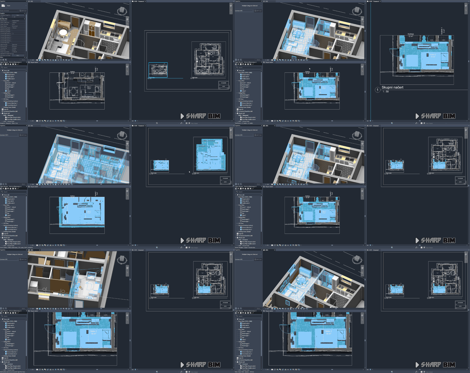
Filtering Elements Visible in a Viewport
 Moustafa Khalil
Introduction
When working with Autodesk Revit API, a common challenge is identifying elements that are visible within a specific viewport on a sheet. Unlike retrieving all elements in a view, filtering only those that appear within the viewport requires additional calculations.
In this article, we will discuss how to achieve this by:
Determining the viewport boundaries on the sheet.
Converting those boundaries to model space coordinates.
Accounting for the view range and depth clipping settings.
Constructing a 3D bounding filter to precisely capture visible elements.
By following this approach, we can efficiently select only the elements that are visible within a viewport, avoiding unnecessary selections and improving automation workflows in Revit.

Let's dive into the implementation details!
Steps to Retrieve Elements Visible in the Viewport:
Obtain the viewport outline – The first step is to get the 2D outline of the viewport on the sheet.
var outline = viewPort.GetBoxOutline();Convert the viewport corners to model space – Since the viewport exists in sheet space, we need to transform its min and max points into model space using the associated view.
 var p0 = outline.MinimumPoint.ConvertToModelSpace(viewPort);
 var p1 = outline.MaximumPoint.ConvertToModelSpace(viewPort);
The
ConvertToModelSpacemethod is defined as follows: (the code is inspired from RPTHOMAS108)public static XYZ ConvertToModelSpace(this XYZ pointOnSheet, Viewport viewPort) { // Get the document associated with the viewport. var Doc = viewPort.Document; // Retrieve the model space view associated with the viewport. var modelSpaceView = (View)Doc.GetElement(viewPort.ViewId); // Retrieve the transformation matrix of the view’s crop box. var viewTransform = modelSpaceView.CropBox.Transform; // Compute the center point of the model space view outline. BoundingBoxUV modelSpaceOutline = modelSpaceView.Outline; var cgModelSpaceUV = (modelSpaceOutline.Min + modelSpaceOutline.Max) / 2; var cgModelSpace = new XYZ(cgModelSpaceUV.U, cgModelSpaceUV.V, 0); // Compute the center point of the viewport outline. Outline vportOutLine = viewPort.GetBoxOutline(); var cgVportOutline = (vportOutLine.MinimumPoint + vportOutLine.MaximumPoint) / 2; // Compute the offset between viewport space and model space. var offset = cgVportOutline.Subtract(cgModelSpace); // Retrieve the view scale. int Scale = modelSpaceView.Scale; // Convert the sheet point to model space using the transformation and scale. var pointOnModel = viewTransform.OfPoint((pointOnSheet - offset) * Scale); return pointOnModel; }Retrieve the view range offsets – If the viewport’s view is a plan view, we extract the top and bottom clip plane offsets.
 var view = viewPort.ViewId.GetElement<View>() as ViewPlan;
 var range = view.GetViewRange();
 var maxZ = range.GetOffset(PlanViewPlane.TopClipPlane);
 var minZ = range.GetOffset(PlanViewPlane.ViewDepthPlane);
Construct a 3D bounding outline – Using the projected points and the view range offsets, we define a 3D outline. This step ensures that elements spanning different Z-levels are considered.
Additionally, a tolerance buffer is applied to the
minZandmaxZvalues. This ensures that elements precisely on the bounding box edges—such as floors with thickness extending below the minimum point—are still included in the selection. Without this, elements that slightly exceed the defined limits would be excluded.double tolerance = 2; p0 = new XYZ(p0.X, p0.Y, minZ - tolerance); p1 = new XYZ(p1.X, p1.Y, maxZ + tolerance);This adjustment guarantees that structural elements like floors, slabs, and other components touching the boundary remain part of the selection.
Apply a bounding box filter – Now that we have the 3D outline, we use it to create a
BoundingBoxIsInsideFilter, which filters elements inside the defined bounding box.var bbxFilter = new BoundingBoxIsInsideFilter(outline); var elements = new FilteredElementCollector(Doc, view.Id) .WherePasses(bbxFilter) .ToElements();Select the retrieved elements – Finally, we update the UI selection to highlight the filtered elements.
UiDoc.Selection.SetElementIds(elements.Select(o => o.Id).ToList());
Final Complete code block
var viewPort = UiDoc.PickElement<Viewport>();
var outline = viewPort.GetBoxOutline();
var p0 = outline.MinimumPoint.ConvertToModelSpace(viewPort);
var p1 = outline.MaximumPoint.ConvertToModelSpace(viewPort);
var view = viewPort.ViewId.GetElement<View>() as ViewPlan;
var range = view.GetViewRange();
var maxZ = range.GetOffset(PlanViewPlane.TopClipPlane);
var minZ = range.GetOffset(PlanViewPlane.ViewDepthPlane);
 double tolerance = 2;
 p0 = new XYZ(p0.X, p0.Y, minZ - tolerance);
 p1 = new XYZ(p1.X, p1.Y, maxZ + tolerance);
outline = new Outline(p0, p1);
var bbxFilter = new BoundingBoxIsInsideFilter(outline);
var elements = new FilteredElementCollector(Doc, view.Id)
.WherePasses(bbxFilter)
.WhereElementIsNotElementType()
.Where(x => x.Category != null && x.Category.HasMaterialQuantities)
.Where(x => x.Category != null && x.Category.CategoryType != CategoryType.Internal)
.Where(x => x.Category != null && x.Category.CategoryType != CategoryType.AnalyticalModel);
List<ElementId> ids = elements.Select(o => o.Id).ToList();
UiDoc.Selection.SetElementIds(ids);
This implementation should help you gather the elements that are actually visible within the viewport.
Subscribe to my newsletter
Read articles from Moustafa Khalil directly inside your inbox. Subscribe to the newsletter, and don't miss out.
Written by

Moustafa Khalil
Moustafa Khalil
I'm Moustafa Khalil El-Sayed, an Egyptian native with a passion for architecture and technology. After completing high school in 1999, I embarked on my journey into architecture, earning my Bachelor's degree in Architecture in 2004. My academic pursuits continued, and I later acquired my Master's degree in Architecture from Wings University. However, my thirst for knowledge extended beyond architectural design, leading me to pursue a degree in Computer Science as well. Driven by a desire to innovate, I began self-teaching computer science, which later empowered me to achieve my Associate degree in Computer Science from the University of the People more easily. Armed with dual expertise in architecture and computer science, I've cultivated a unique skill set that blends creativity with technical acumen. My career has taken me across borders, from Egypt to Oman and the UAE, where I've honed my skills as an architect. As a graduate architect and a proficient .NET BIM Solution Developer, I specialize in translating unique visions into tangible realities. My role extends beyond conventional architectural practices; I leverage technology to streamline processes and enhance project outcomes. My journey into programming began with developing script-based Excel tools to augment project management efforts, notably during the Sharm El Sheikh development. Over time, I expanded my programming prowess to address practical challenges encountered in bridging Revit and AutoCAD within my professional sphere. Several of my applications, born from this evolution, have gained recognition, with some even being featured on the Autodesk website. I am committed to pushing boundaries and continually enriching the intersection of architecture and technology, ensuring that my clients benefit from cutting-edge solutions tailored to their needs.