A Breadboard Computer
 Kyle Moore
While I based my hardware designs completely off of Beneater’s videos and schematics, many lessons were learned while building and troubleshooting this machine. Before this project, the most ambitious hardware projects involved using an Arduino, sensors, and their bespoke API’s that did everything but write the code for you. This project, above all, made me an expert wire stripper, but beyond that gave me insight into how any computer interfaces with its clock, memory and I/O devices, and deepened a growing passion for the lowest level of software engineering.

|
|
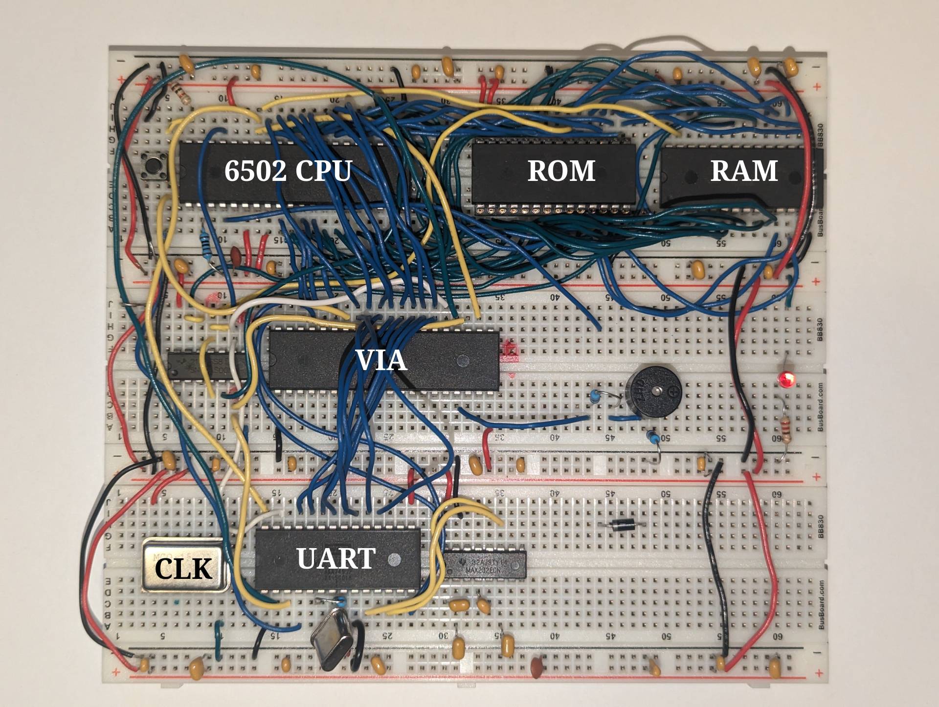
My completed computer with important components labeled |
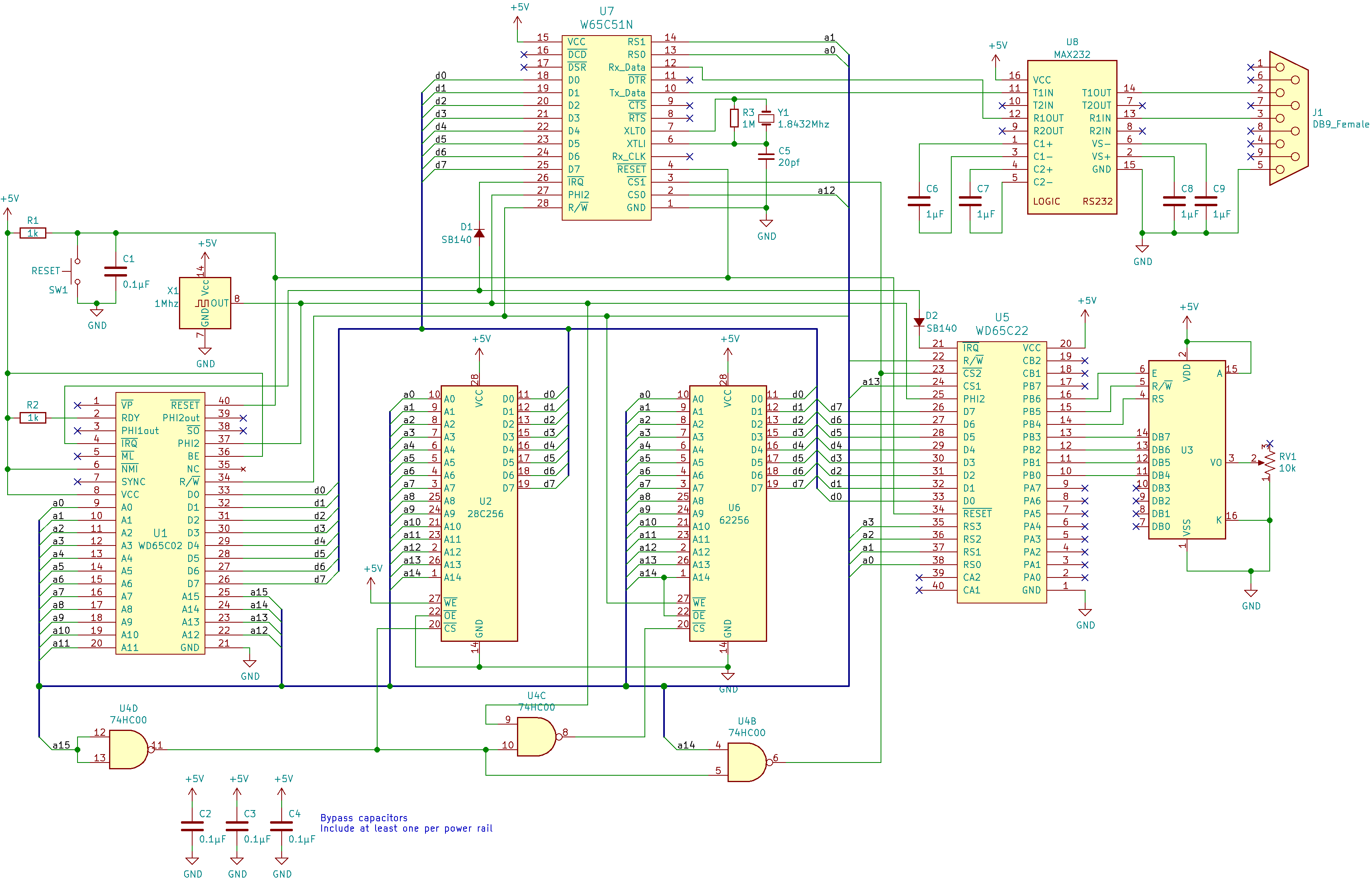
My computer consists of six major parts. The CPU, an 8-bit a 50-year-old processor, which even at the time was a budget, low powered option. A blazing fast 1 MHZ clock. The memory, which consists of two chips, an EEPROM (electronically erasable programmable READ ONLY MEMORY) that serves as the computer’s only nonvolatile memory, as well as an astonishing 4kb of RAM (note the smallest size of a file in windows in 1kb!) A VIA (versatile interface adapter) which acts as a simple method of I/O, and a ACIA (Asynchronous Communications Interface Adapter) which is used to communicate over UART to a terminal. The actual construction of the computer, as I like to explain it, was simply wiring up a motherboard.

|
|
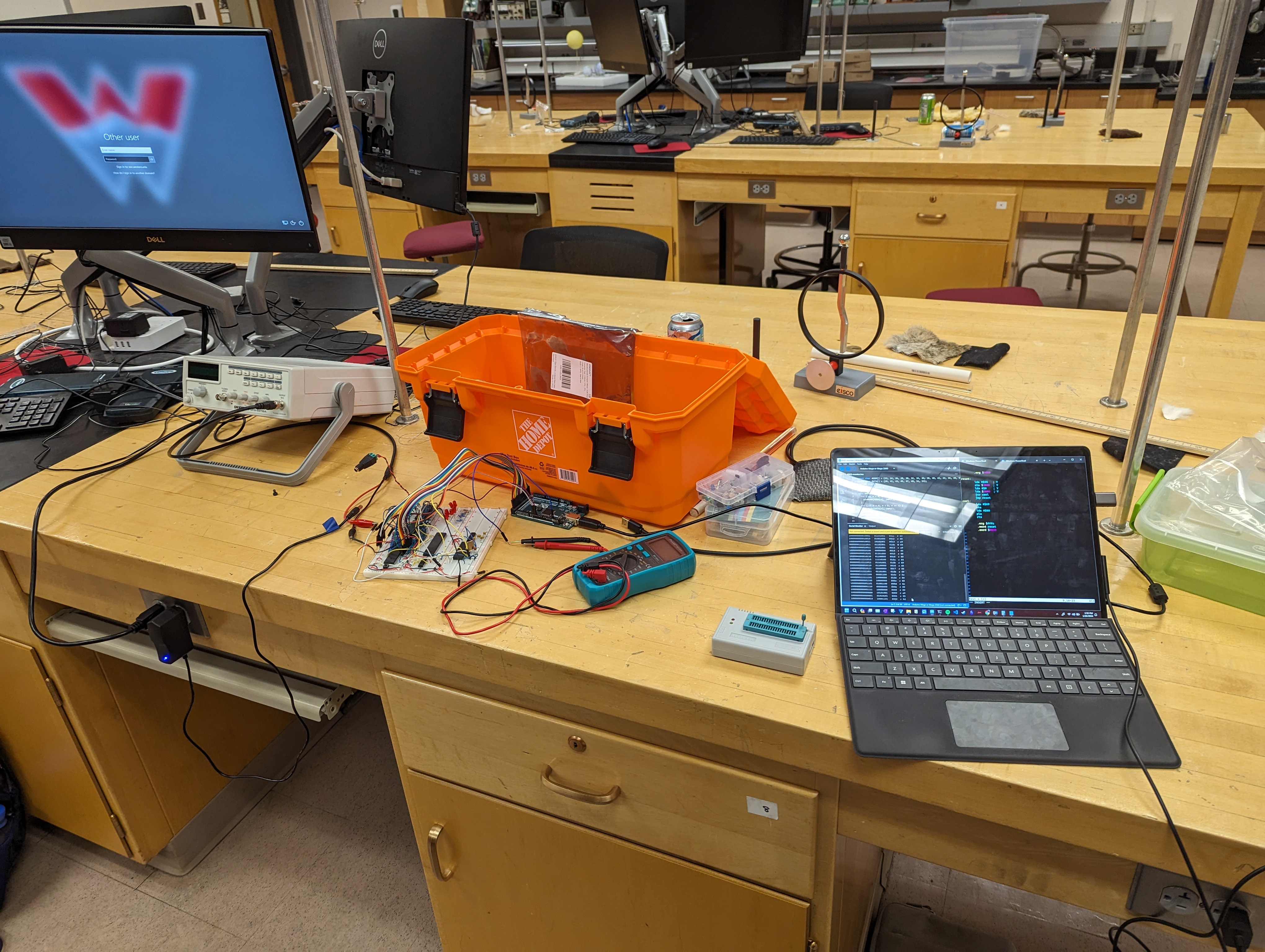
My initial debugging setup in a physics lab |
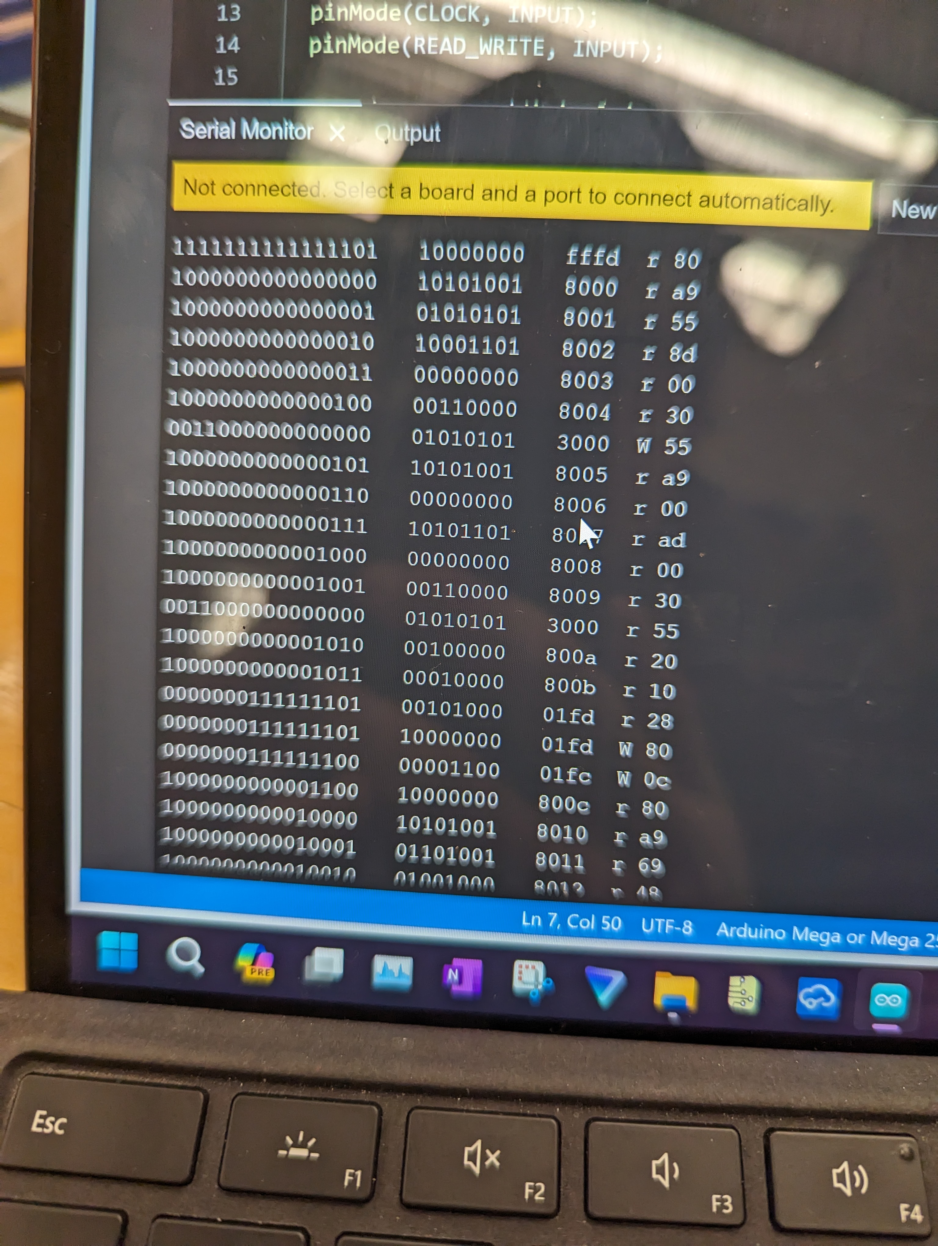
The biggest challenge I faced throughout the entire build process, was mis-wiring one of hundreds of wires, that would mean the computer would fail to show any signs of life. No error messages, no error codes, nothing. My first shot at troubleshooting involved using the school’s ancient waveform generators, from the physics department, to provide a close to 1 hertz clock that could be used to step through the instructions on the computer in a manner readable by an Arduino hooked up to the data pins. Via this method, I could read in the contents of memory being fed into the CPU, and write down the program in machine code. To this day I can tell you that 0xA9 is the instruction load immediate into accumulator, 0×8D is store accumulator immediate, 0×20 is jump to subroutine, etc. Through this method, I found out that I fundamentally misunderstood how I needed to wire the RAM, and saved hours of frustration. I also learned that this method of troubleshooting was incredibly helpful, and needed a more permanent way of doing so. I decided to invest in a simple 8-channel USB logic analyzer, that I still use not only to troubleshoot hardware, but also to debug software.

|
|
A closer look at the debugging process |
Subscribe to my newsletter
Read articles from Kyle Moore directly inside your inbox. Subscribe to the newsletter, and don't miss out.
Written by
