Exploding your brain with ATMEGA328P!
 Raunak Biswas
ATMEGA328P used in the Arduino UNO R3, is a beginner-friendly microcontroller widely used for embedded development and creation.
Let’s try to understand the different components of our beginner-friendly microcontroller!
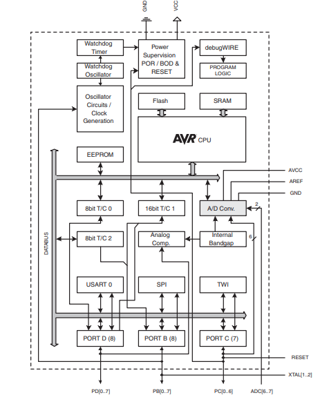
This is a sketch of the components that this processor has. Each and every component specialises in a certain task that makes development with the Arduino microcontroller very easy and fast!
Let’s now try to understand each component of this processor in detail, starting with:-
The CPU
The CPU (Central Processing Unit) is the brain of a computer. It's a piece of hardware that carries out a computer's instructions. The CPU is responsible for performing basic arithmetic, logical, and input/output operations.
The ATmega328P microcontroller has 32 general-purpose working registers. Each register can store 8 bits of data, which can be used for various data storage and manipulation tasks. The processor can work at a good speed of 16 MHz.
The Memory
Memory is the microprocessor's storage area. It is where we store essential information and data that lets us make the processor do a lot of interesting stuff. In ATMEGA328P, there are three types of memory.
Flash memory
The flash memory is the largest storage component in the processor with a descent 32K bytes of storage space. It is the place where the processor stores the executable instructions that we write in the C++ coding language.
It’s a type of ROM with a write/erase cycle of around 10,000 times, which means the instructions in it can only be rewritten 10,000 times. The data in the flash memory can’t be accessed randomly, the data can only be read on a block-wise basis. A small portion of the flash memory contains the boot code for the processor.
SRAM
SRAM (Static Random-Access Memory) is a type of volatile memory used to store temporary data like variables and the program's stack, crucial for the Arduino's operation, and is a limited resource that needs to be managed carefully.
The SRAM in the Arduino microcontroller only has 2 kilobytes of limited storage space. This 2kb of ram contains all the global variables, stack, heap, and also the static variables. It has 2048 unique memory addresses out of which the first 255 of the addresses contain code which is essential for running the arduino, and the rest can be manipulated as we like.
EEPROM
EEPROM (Electrically Erasable Programmable Read-Only Memory) is a type of non-volatile memory that allows you to store data even after the Arduino is powered off, acting like a small, persistent storage space. In the Arduino, the flash memory is the place where the program is stored, and EEPROM is just for nonvolatile data. In general, flash is quicker to read from, the both take a bit of time to write to.
The EEPROM in the Arduino Uno has only 1 kilobyte of memory. We can use the
EEPROMlibrary to read and write data to it. Unlike flash memory, EEPROM can be rewritten 100,000 times.
Communication
The Arduino is a microcontroller that is used to communicate and control different peripheral devices. It has a lot of different interfaces and protocols that make communication between different peripherals easier, both internal and external.
Databus
A data bus is a system of connections that allows two or more devices or components to exchange data in an organized manner, like a pathway for information.
A data bus facilitates communication and data transfer between an Arduino microcontroller and other devices, such as sensors, I/O expansion devices, or other peripherals.
TWI
- TWI (Two-Wire Interface) refers to the hardware and software abstraction used for I2C (Inter-Integrated Circuit) communication. It allows the Arduino to communicate with I2C-compatible devices using a two-wire bus (SDA and SCL). It is used with either one or two wires, enabling protocols for parallel processing.
SPI
- Serial Peripheral Interface (SPI) is a synchronous serial data protocol used by microcontrollers for communicating with one or more peripheral devices quickly over short distances. It is duplex and is used with a clock for transmission.
USART
USART (Universal Synchronous/Asynchronous Receiver/Transmitter) is a hardware interface for serial communication. It allows devices to transmit and receive data bit by bit and can be used in both synchronous and asynchronous modes.
It is a simple serial communication protocol allowing devices to exchange data using two wires. The
Serialobject in the Arduino used to view things in the serial terminal also uses USART.
PORTS
- Ports refer to groups of pins (specifically, digital and analog) used for input and output, allowing for faster and more efficient control of multiple pins at once through port registers. In Arduino, ports can be directly manipulated with bits for very fast communication.
Current and power
The ATMEGA328P is a very dynamic device, with both analogue and digital signal capabilities. It can be used to both read and write analogue signals, which is very useful for hardware and embedded development.
A/D CONVERTER
An A/D converter (Analog-to-Digital converter) in Arduino is a hardware component that converts analog signals (continuous voltage values) into digital values (A high or a low) that the microcontroller can process.
The ATMEGA328P has 10-bit ADCs, meaning they can represent the analog input as a value between 0 and 1023. It uses the
analogRead(pin)function to read the ADC value
Analog Comparator
The analog comparator in the Arduino UNO is a hardware module that compares two analog voltage signals and outputs a digital signal based on which voltage is higher.
It compares the voltage at AIN0 (pin D6) and AIN1 (pin D7).
If AIN0 > AIN1, the Analog Comparator Output (ACO) is set to HIGH.
If AIN0 < AIN1, the ACO is set to LOW.
Internal Bandgap
- The internal bandgap in the Arduino refers to a built-in voltage reference of approximately 1.1V. It provides a stable reference voltage that can be used for analog-to-digital conversion (ADC) or as a comparison reference for the analog comparator.
Power-on Reset
- The Power-on Reset (POR) is a circuit that automatically resets the microcontroller when power is first applied. It ensures that the microcontroller starts in a known state, preventing undefined behavior during startup. When the supply voltage (Vcc) rises from 0V to a stable level, it is triggered.
Brown-out Detection
- The Brown-out Detector (BOD) monitors the supply voltage (Vcc) during operation. If the voltage drops below a certain threshold (typically 2.7V or 4.3V, depending on fuse settings), it triggers a reset. This prevents the microcontroller from executing erratic instructions due to insufficient voltage.
Reset
- The reset function on the Arduino UNO is used to manually reset the board. When pulled LOW, the board restarts, clearing all running instructions. It can also be triggered by the watchdog timer or external reset signals.
DebugWIRE
- The debugWIRE is a debugging interface used in ATmega328P (the microcontroller on Arduino UNO). It allows in-system debugging using only one wire (the RESET pin), making it efficient for low-pin-count microcontrollers.
Clock
In the ATmega328P processor, all tasks need to be precisely timed. This is where the clock comes in. The clock in the processor runs at 16 MHz.
Timers/Counters
The Timers/Counters in the ATMEGA328P are hardware modules used for precise timekeeping, counting events, and generating PWM signals.
The ATmega328P microcontroller on the UNO has 3 timers:
Timer0 → 8-bit (used for
millis()anddelay()).Timer1 → 16-bit (used for precise timing and PWM).
Timer2 → 8-bit (used for timing and PWM).
Watchdog Timer
The Watchdog Timer in the ATMEGA328P is a hardware timer that automatically resets the board if the program becomes unresponsive or enters an infinite loop.
The WDT is a countdown timer that runs continuously. It must be periodically reset using
wdt_reset()to prevent a reset. The timeout periods can range from 15 ms to 8 seconds.
Oscillator Circuits/Clock Generation
The Arduino uses an oscillator circuit to generate a stable clock signal for the ATmega328P microcontroller, ensuring proper timing and synchronization.
Main Clock:
16 MHz crystal oscillator (external).
Provides the primary clock signal for the CPU and peripherals.
Internal Oscillator:
8 MHz RC oscillator (less accurate).
Used as a fallback or for low-power modes.
Watchdog Timer Oscillator:
- 128 kHz clock used for the WDT.
Subscribe to my newsletter
Read articles from Raunak Biswas directly inside your inbox. Subscribe to the newsletter, and don't miss out.
Written by
Raunak Biswas
Raunak Biswas
Innovative developer with a passion for continuous learning and expertise in cutting-edge technologies. Proficient in C, C++, AVR Assembly, Python, and electronics. Enthusiastic about creating seamless user experiences and optimizing performance. Always eager to explore new tools and frameworks to stay ahead in the tech world.