How to Read Circuit Diagrams: A Beginner’s Guide
 Rishi Srivastava
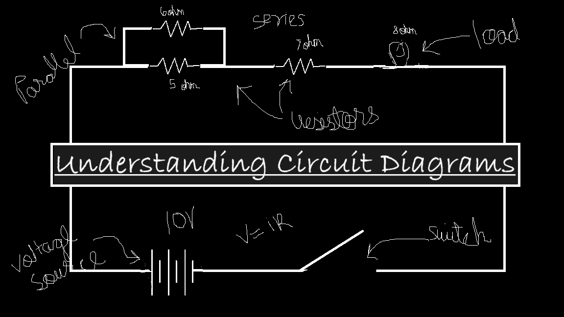
Ever looked at a circuit and felt lost?
"Ahh, what are these arrows and zigzag lines??"
Were these the words spinning in your head when you first saw that plain, daunting sketch in your circuit theory book? Do you want to decode those confusing circuits and earn the respect of your classmates? Worry not! I’m here to make those intimidating circuits a cakewalk for you.
Understanding electrical circuits is integral to mastering electronics and fully experiencing the joy of this fascinating art. Yes, you heard that right—circuit diagrams are an art. They simplify our understanding of how electricity flows, how components interact, and how to prevent accidental disasters (like blowing up an expensive component :).
With just one diagram, you can pre-analyze everything—the voltage across each component, the current flowing through it, the power it dissipates, and much more—all before even turning the switch ON. Fascinating, isn’t it?
Let’s dive in!
What This Article Covers:
📌 What is a circuit diagram? – Understanding the basics and key terms.
📌 Common symbols and meanings – Breaking down basic components.
📌 Understanding connections – Seeing the flow in any circuit.
📌 Reading a circuit – Step-by-step guide to decoding circuits.
📌 Practical example & questions – Breaking down a real circuit.
📌 Important tips – Pro tricks to read circuits faster.
📌 Conclusion & References
What is a circuit diagram?
The electric circuit has is scientifically defined as:
“An electric circuit is a closed-loop conductive pathway that allows electric current to flow, typically consisting of an energy source, conductive elements, and electrical components that regulate, control, or utilize the flow of charge according to established physical laws such as Ohm’s Law and Kirchhoff’s Laws.”
Now, let's simplify things and understand the basic idea of a circuit in an intuitive way, without technical jargon.
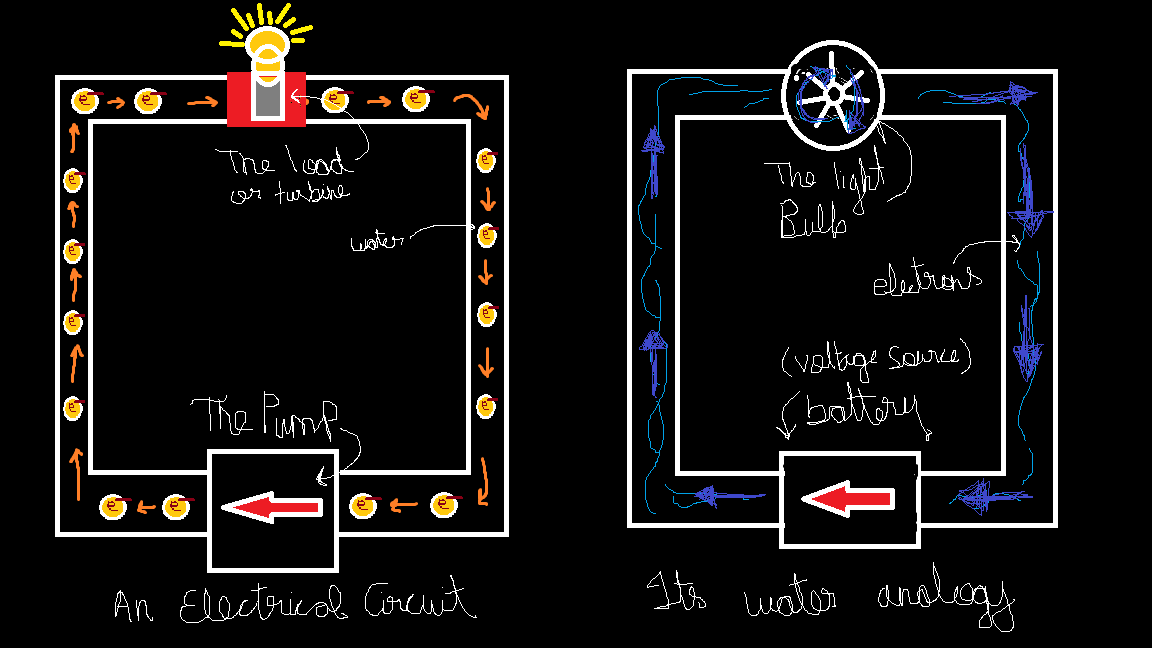
An Analogy: Think of Water Pipeline
What all things are the key elements in this system.
The Pipeline: Contains the water.
The Pump: Which pushes or forces water in a certain direction.
The Water: Goes all arounds the pipe,
A Turbine: The load attached to the pipeline.
The pushed water in the pipeline which goes all around in the closed looping pipeline, now as this water rotates the turbines installed inside the pipe, generating power or in very simple terms "does something". We can say the pump transferred power from itself through the water to the turbine and the turbine used that energy to do its "work". (Make sure to fully grasp this analogy has it will help a lot in the upcoming sections).
Now think, of a metallic wire. Metals contain free electrons (electrons which are 'free' to 'flow' in the metal body, i.e. here the wire). The wire is our closed pipeline which contains electrons, the water, which is pushed by our battery, the pump, which goes into the load, the turbine, and in simple terms transfer their energy to the load so that the load and "do its work". Water flows to the turbine, the turbine rotates, electrons go to the load, e.g. an LED, it glows. Keep it that simple for now.
After this short discussion, let's try to define the terms with our own understanding.
Circuit - A closed path through which electric current flows, consisting of an energy source, conductive connections, and electrical components.
Battery - A device that converts chemical energy into electrical energy, providing a voltage (the push for electron) source for a circuit.
Load - Any component or device in a circuit that consumes electrical energy to perform work, such as a resistor, motor, or light bulb.
Let's continue our discussion forward.
Now imagine we had a pump whose power level can we varied, i.e., the pressure provided by it to push the water can be controlled. Now what does that do? YES! Its changes the speed by which the water is flowing through the pipe. Does this have any effect on our turbine? YES! The turbine moves faster, i.e. it is getting more power by the water. Now the new terms which we introduced here 'pressure' and 'speed of water' are called 'voltage' and 'current' in the world of electricity.
Voltage and Current
First, we'll deal with voltage, shall we? As mentioned before, voltage can be understood as the push provided by the pump or, in this case, the battery. By changing its value, we can directly affect the speed or amount of current.
Now, coming to current, it can be understood as the speed at which charges (here, electrons) flow through the circuit. The faster they move, the more energy they transfer.
Now that we have laid a solid intuitive base for the most important terms of the electric circuit, its time to go technical and bring the mathematics into picture. (Don't worry, Its gonna be as intuitive as it was till now)
Mathematical Analysis: \(V = IR\)
The letter \(I\) and \(V\) denotes current and voltage respectively. The current \(I\) is measured in ampere (A) and voltage \(V\) is measured in volts (V). As we understood that voltage and current as directly related, we can draw a mathematical relation here: “voltage is directly proportional to current I”, which resolves by introducing a constant called resistance.
We get the famous result.
$$V=IR$$
Resistance
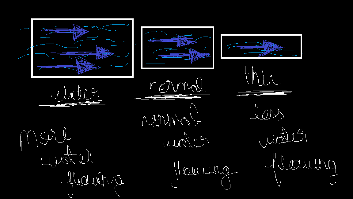
What is resistance, you ask? It is the obstacle that resists the flow of charges through it and affects the flow rate. Too hard to grasp? Let's go back to the water analogy. As we all know, pipes have sizes, specifically their diameter. Now, imagine a big, BIG, BIG pipe. Water will flow through it so easily, and a lot of it, wouldn't it? Now, imagine narrowing the pipe. Even if we maintain the same pressure, the overall amount of water flowing through (the flow rate) will decrease because the pipe is restricting the flow. Similarly, in electric circuits, resistance determines how much the circuit opposes the flow of current.
Is the circuit resisting? YES! Everything resists the flow of current, or we can say that they allow current to flow only up to a certain limit. Materials that provide the least to negligible resistance are called conductors (e.g., metals). On the other hand, materials that provide maximum resistance are called insulators (e.g., wood). Now, the metal wire through which current is flowing also provides some resistance, but in an ideal world, we assume the resistance of the wire to be zero (a perfect conductor).
Hence to compensate for this, we as a rule, always add a resistor (coming up in a moment, stay with me) into the circuit whose resistance value is considerable and is huge compared to that of the wire hence in the ideal world we only need to consider the resistance of that resistor and not of the wire. This ensures that our ideal assumptions are not drastically different from the real world, making calculations more practical.
Resistor
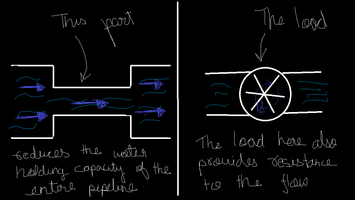
A resistor, as you might have guessed, is “a device that provides a specific amount of resistance based on our needs”. Imagine a small-sized pipe fitted between a normal-sized pipe. Regardless of the resistance of the normal pipe, the flow now depends entirely on the size of the smaller pipe. Similarly, does the load also provide resistance? Of course! Wouldn’t a turbine act as an obstacle from the perspective of the water trying to flow? Every load has its own resistance, which it adds to the circuit. (In fact, resistance is the very principle behind how these electrical components function! We'll dive deeper into this in upcoming articles.) It is measured in ohm.
Sooo, to sum up whatever we understood till now. Voltage, Current, Circuits, Resistance and the relation \(V=IR\). Lets move towards learning about common components symbols and their meanings.
Common symbols and meanings
Obviously, we cannot always draw intricate diagrams or describe a circuit using words alone. Hence, we use symbols. Here, we’ll discuss the symbols for various circuit components we’ve covered so far.
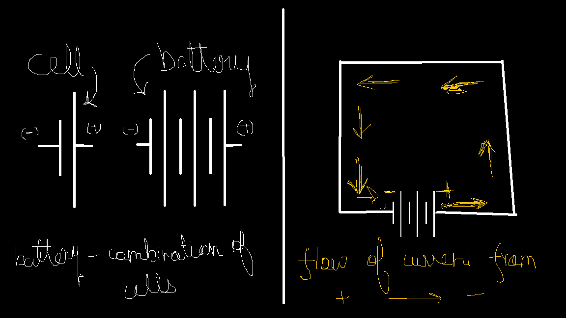
In a battery symbol, the longer side represents the positive terminal, while the shorter side represents the negative terminal. What are these terminals? Remember when we discussed the direction of water flow in relation to the pump? The same concept applies here. The terminals indicate the direction of current flow—current always flows from the positive terminal to the negative terminal. (For those wondering about charge movement and terminal polarities, don’t worry! We’ll clarify this in upcoming articles.)
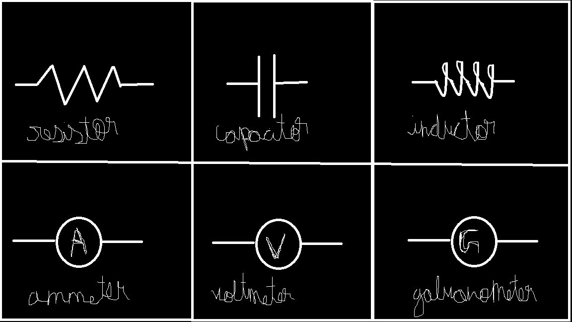
Now, let’s look at the symbols for a resistor, capacitor, and inductor, and a chart of common circuit symbols.
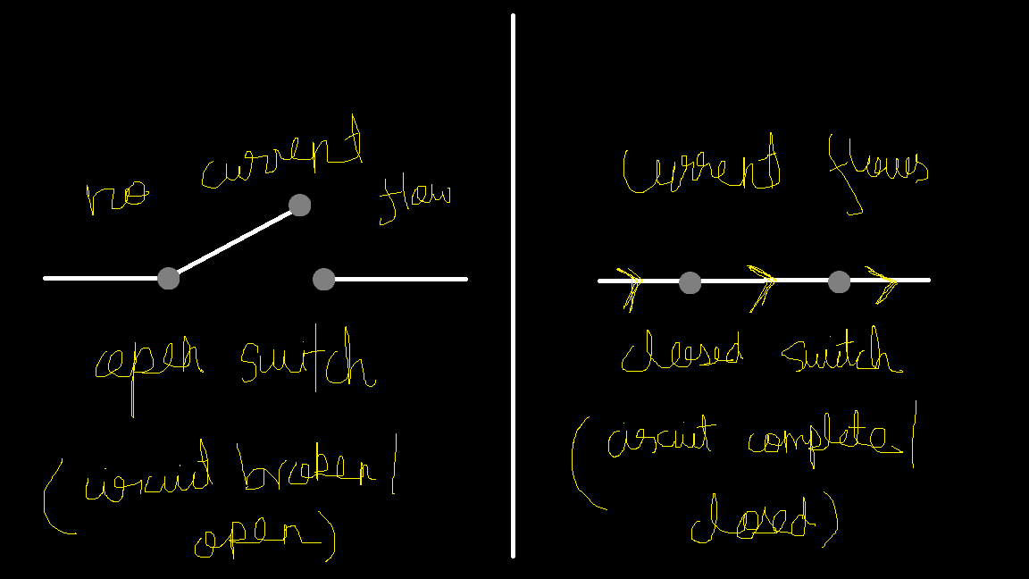
Also we a component called switch, which is exacly what its name suggest. Its turns ON/OFF the circuit by Closing(Completing)/Opening(Breaking) the circuit. Now tell what’s current in the circuit in the cover picture:)
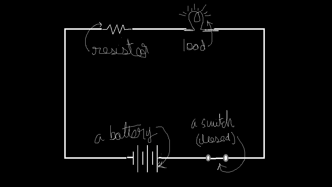
Lets put all of them together and make a complete circuit.
Understanding connections
Now, let’s understand how components connect in a circuit. We have our basic circuit: a voltage source (battery) \(V\), current \(I\), resistance \(R\), and a load (an LED). As mentioned before, current flows from the positive terminal of the battery to the negative terminal through the resistor and the load.
Since \(V\) and \(R\) are values we set, we can determine the current using Ohm’s Law:
$$I=\frac{V}{R}$$
Series Connection
Simple? Now, let’s go further. Imagine there are two resistors in the circuit, placed one after the other. What happens now? We still know \(V\), but what about \(R\)? Will the total resistance be equal to \(R_{1}\), \(R_{2}\), their product, or their sum?
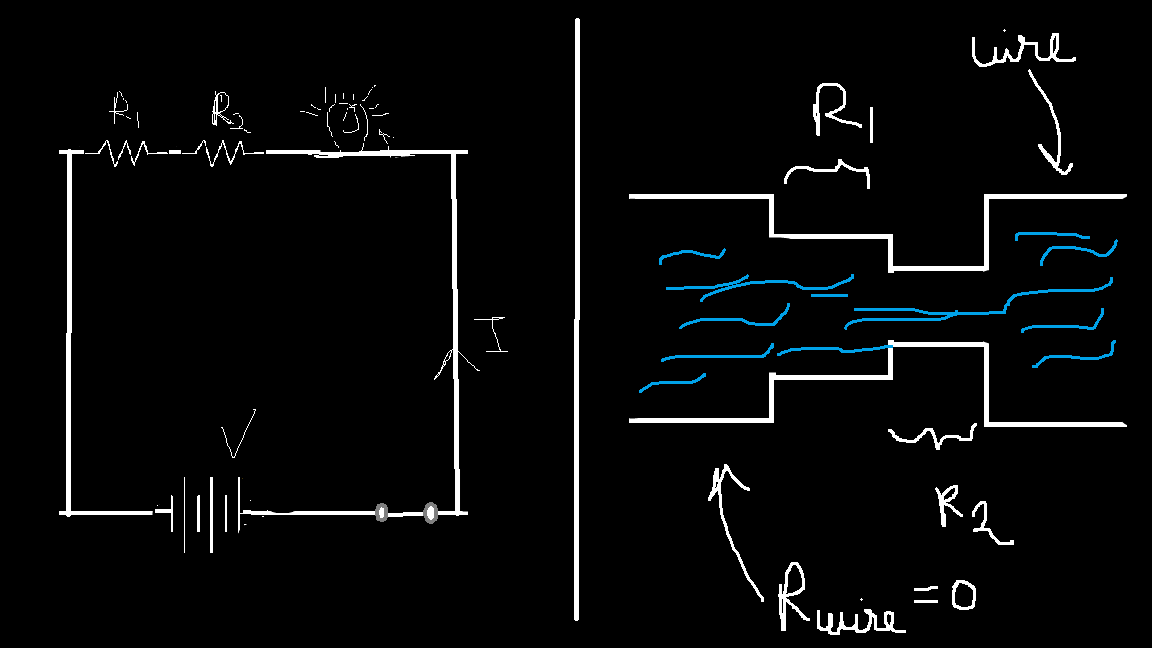
Think of it like water flowing through two different-sized smaller pipes placed at different points in a larger pipeline. The total resistance to flow will be the sum of the individual resistances. If the first pipe restricts x amount of water and the second restricts y amount, the total restriction will be x + y. Similarly, in a series circuit, the total resistance is given by:
$$R_{total}=R_{1}+R_{2}$$
Also called the “equivalent resistance”, \(R_{Equivalent}\) of the circuit (because if we replace the two resistors with a single resistor with the value \(R_{1}+R_{2}\) then the values of current for the same value of voltage will be the same). i.e.
$$V=I(R_{1}+R_{2})$$
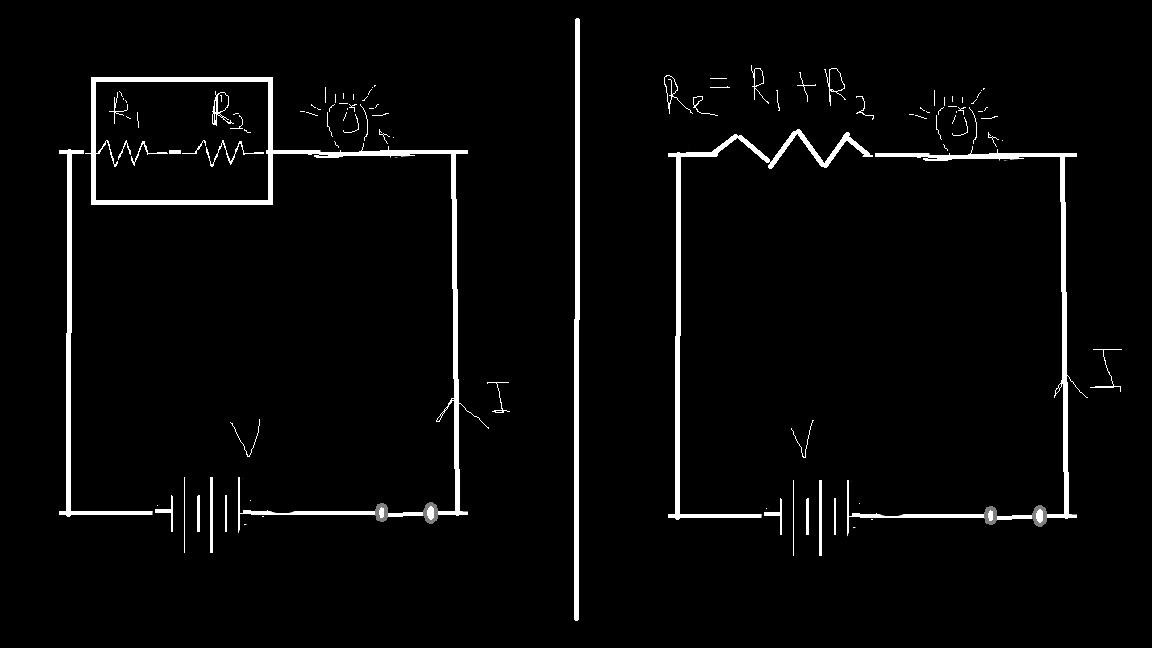
This type of circuit, where resistors are placed one after the other, is called a series circuit, meaning the resistors are connected in series. Since the path remains the same, the same amount of current flows through both resistors.
Deriving \(R_{Equivalent}\) In Series
Now, some may ask: If the current is the same but the resistance values are different, then according to the relation \(V=IR\), will the voltage across the two resistors vary? Like \(V_{1}=IR_{1}\) and \(V_{2}=IR_{2}\)? YES!
Back to the water analogy—imagine the pressure near the mouths of two different pipes. Would it vary? Why, you ask? Since the same amount of water is flowing through both, think of each pipe individually:
The same water flows through a small pipe (less pressure).
The same water flows through an even smaller pipe (higher pressure).
Similarly, in an electric circuit, the voltage across each resistor depends on its resistance. (Did this sparks some deep questions—we’ll cover them up in future articles:) Now, the sum of these two voltages is equal to the total voltage applied by the battery. \(V_{1}+V_{2}=V\)
A little bit of math:
$$V_{1}+ V_{2}=IR_{1}+IR_{2}$$
$$V_{1}+V_{2}=I(R_{1}+R_{2})$$
See where this is going? Using Ohm’s Law:
$$V=I(R_{1}+R_{2})$$
$$R_{Equivalent}=R_{1}+R_{2}$$
Now this fundamental formula can go upto \(N\) number of resistors connected in series. i.e.
$$R_{Equivalent}=R_{1}+R_{2}+R_{3}+...+R_{N}$$
Paralle Connection
Okayy, so is this the only type of circuit you'll deal with? Nope. There's another. What is you get something like this.
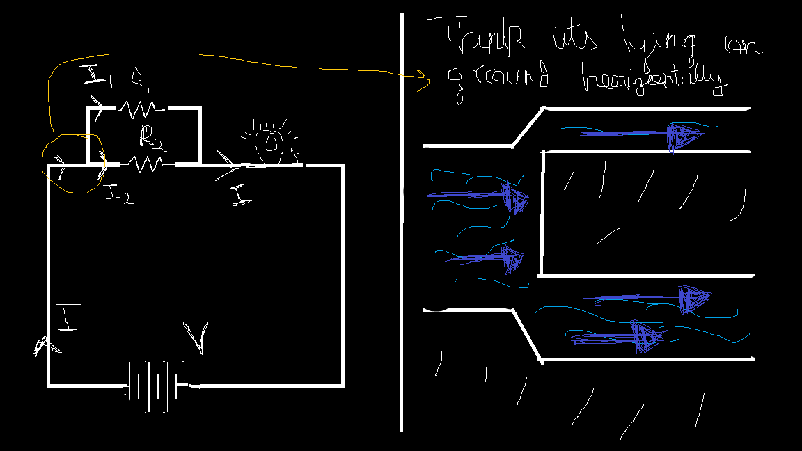
So now the two resistors are in different paths we see. The thing here to notice is that “they are connected end to end and hence are said to be connected in parallel”. Hmm, What happens now?
Let’s go back to our water analogy. This time, the water in the pipe has two different paths to flow through. But how much water will flow through each path?
That depends solely on the resistance of each path because voltage remains constant here. Huh what?—yea yea. Think about it—both paths connect at the same points (like two pipes that branch out from the same source and meet at the same exit). Since these points are common, the pressure (voltage) at these points must be the same for both paths.
So, the path with less resistance will allow more water (current) to flow, while the path with higher resistance will allow less. Mathematically speaking,
$$I_{1}=\frac{V}{R_{1}}, I_{2}=\frac{V}{R_{2}}$$
See? Just like current was constant in series circuits, here voltage remains constant across both resistors. Also, we can see that “current and resistance are inversely proportional“.
So how do we find equivalent resistance?
Deriving \(R_{Equivalent}\) in Parallel
Recalling the point where the water splits into two pipes, let’s now focus on the end, where the two streams merge back into one.
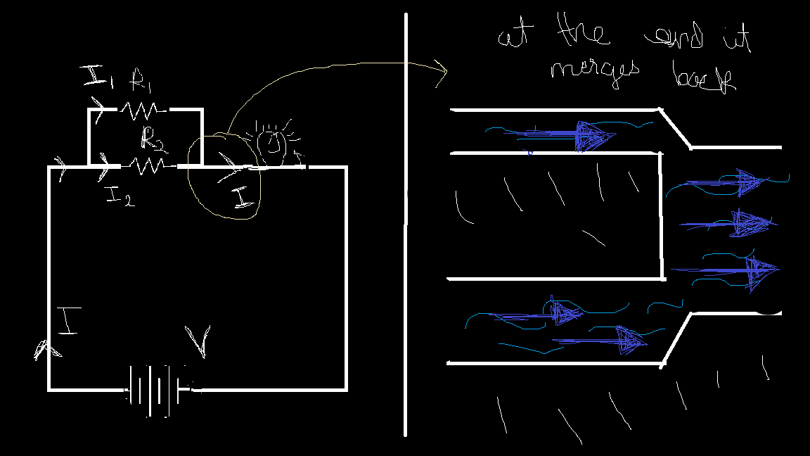
In terms of current, this means:
$$I=I_{1}+I_{2}$$
where \(I_{1}\) and \(I_{2}\) are the currents flowing through each resistor.
Using Ohm’s Law \(V = IR\), we substitute:
$$I=\frac{V}{R_{1}}+\frac{V}{R_{2}}$$
Factor out \(V\):
$$I=V(\frac{1}{R_{1}}+\frac{1}{R_{2}})$$
Since Ohm’s Law also states \(V=IR_{Equivalent}\), we get:
$$\frac{1}{R_{Equivalent}}=\frac{1}{R_{1}}+\frac{1}{R_{2}}$$
This is the formula for the equivalent resistance in a parallel circuit. We can extend this even further to \(N\) resistor connected in parallel.
$$\frac{1}{R_{Equivalent}}=\frac{1}{R_{1}}+\frac{1}{R_{2}}+\frac{1}{R_{3}}+...+\frac{1}{R_{N}}$$
Now that we have covered how current flows in a circuit, it’s time to move on to the interesting part—decoding an actual circuit. First, we’ll analyze two basic circuits, and then we’ll explore the different types of questions that are commonly asked and how to approach them effectively.
Reading a circuit
Since this is for beginners, we’ll start with simple circuits and gradually move on to more advanced concepts as we progress.
Steps to Analyze a Circuit:
1️⃣ Note down the given data – Identify the values of voltage, current, or resistances provided.
2️⃣ Find the equivalent resistance – Apply the series and parallel resistance rules to simplify the circuit.
3️⃣ Use Ohm’s Law – Apply \(V=IR\) to solve for the unknowns.
Now, let's break it down with an example!
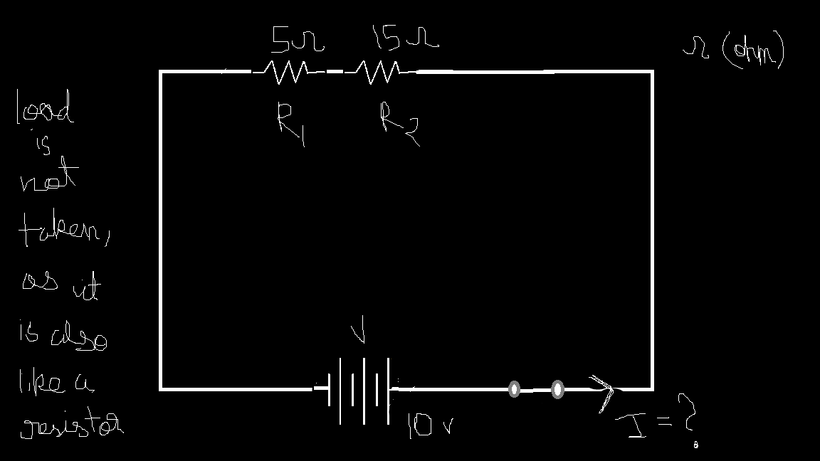
Step 1. Given: \(V=10v\), \(R_{1}=5ohm\), \(R_{2}=15ohm\). To Find: I
Step 2. Using series resistance formula we get \(R_{total}=R_{1}+R_{2}=5+15=20ohm\)
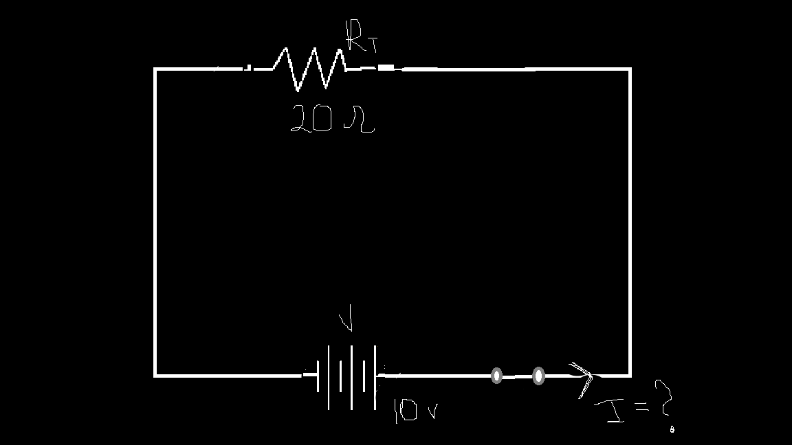
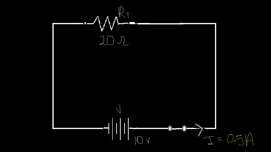
Step 3. Using \(V=IR\) total, We get \(I=\frac{V}{R_{total}}=\frac{10}{20}=0.5A\)
Practical example & questions
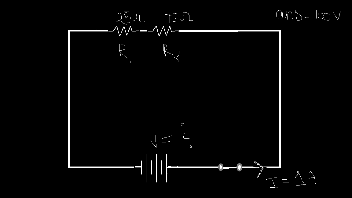
Here are some more examples for you to go through. The answers have been provided. Comment the exact step by step procedure below to show you understood it.
1.
2.
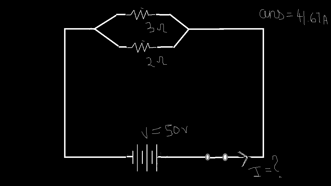
3.
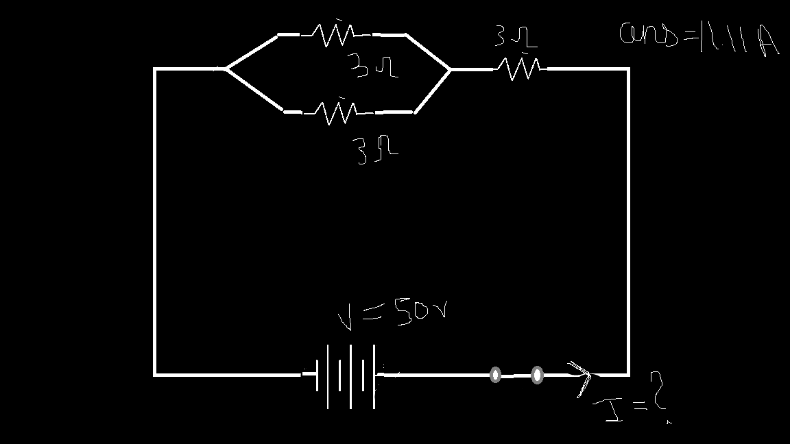
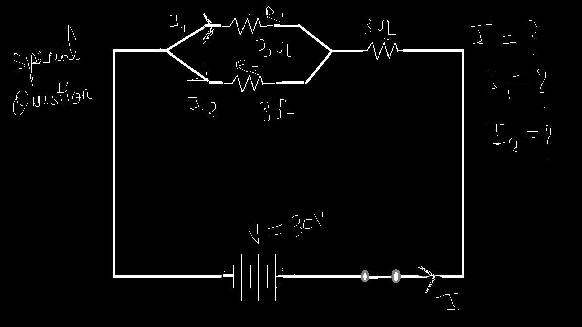
This last one is a special type which maybe confusing for some beginners. The answer to this will be provided in next article with each step. If you know how to solve it, you may comment your answers below and i’ll verify it.
Important tips
Here are some tricks to solve the series and paralle circuits faster and quickly.
If we have same \(N\) resistors in
In series: \(R_{total}=NR\)
In parallel: \(R_{total} = \frac{R}{N}\)
For parallel solving two resistors, we have an formula: \(R_{total} = \frac{R_{1}R_{2}}{R_{1}+R_{2}}\)
Apart from this, two other important facts
In serier: The total resistance is always greater than the largest resistance.
In parallel: The total resistance is always smaller than the smallest resistance.
Conclusion & References
By now, you should have a clear understanding of how electric circuits work—from the fundamental concepts of voltage, current, and resistance to analyzing series and parallel circuits using Ohm’s Law. We explored real-world analogies to make these ideas intuitive and learned the step-by-step approach to solving circuit problems.
Mastering these basics sets the foundation for tackling more complex circuits in the future. As we move forward, we’ll dive deeper into circuit components, advanced problem-solving techniques, and real-world applications. So, stay curious and keep experimenting—because understanding circuits is the first step toward building incredible electronic systems!
For future articles, we’ll go through capacitors, inductors and even more advance components of the circuit. Also I am open to constructive critisim and reviews to update and improve my content.
Some book recommendation for further reading:
Fundamentals of Electric Circuits
Book by Charles K. Alexander and Matthew N.O. Sadiku
Electrical Engineering: Principles and Applications
Book by Allan R. Hambley
Engineering Circuit Analysis
Book by William H. Hayt
The Art of Electronics
Textbook by Paul Horowitz and Winfield Hill
Subscribe to my newsletter
Read articles from Rishi Srivastava directly inside your inbox. Subscribe to the newsletter, and don't miss out.
Written by

Rishi Srivastava
Rishi Srivastava
BTech ECE student | Passionate about electronics, AI, and GPUs. Writing to make tech simple. Founder of SiliconPen.com.