Cyberstorm 2025 Writeup: Open The Flood Gates [by Windows 9/11]
 Nayanesh
Category: Hardware
Team Name : Windows 9/11
Author: Nayanesh
CTF Writeup: Open The Flood Gates Hardware Challenge
Challenge Description
Franky used to work at a Dockyard, but never understood how the complex network of gates and channels worked there. So, the Dock Master drew a diagram for him which he could understand. This helped him instantly understand the workings, are you as smart as Franky?

Provided Information/Files
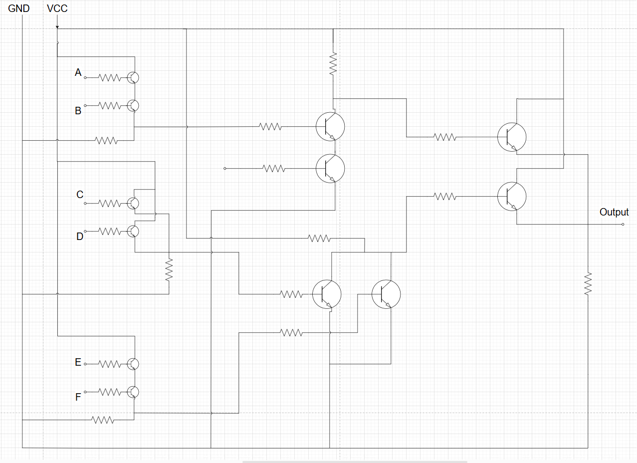
Image of a circuit containing BJT connections with 6 inputs and 1 output (either 1 or 0).
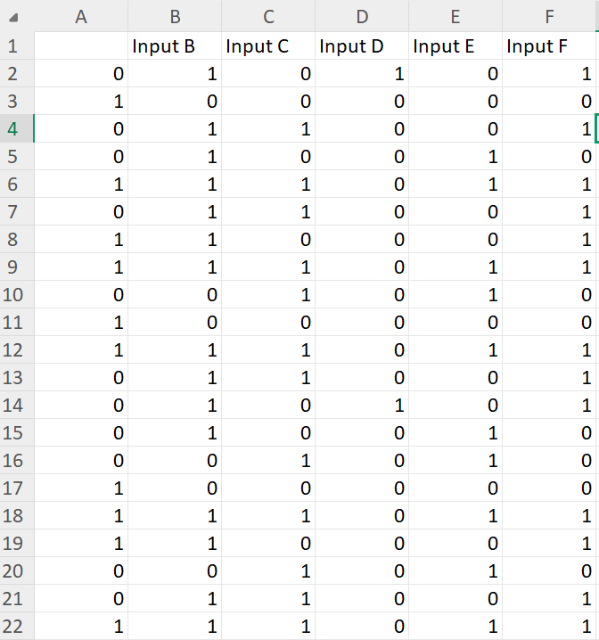
A xlsx file containing input values.
Initial Clues & Analysis
The provided circuit image suggested a logical computation based on BJT connections. Given that the circuit had 6 inputs and 1 binary output, my first step was to analyze the logic governing the output.
Investigation Path
Step 1: Circuit Analysis
Since analyzing the circuit manually would be time-consuming, I used Claude AI to examine the circuit. I provided the circuit image along with the prompt:
"Explain this circuit and all outputs for all possible inputs. Trace the signal path and provide the 64 outputs."
Claude AI provided the following Boolean expression:
(NOT A AND NOT B) OR (NOT C AND NOT D) OR (NOT E AND NOT F)
which can be rewritten as:
(!A • !B) + (!C • !D) + (!E • !F)
Step 2: Constructing a Truth Table
Using this Boolean expression, I generated the truth table for all 64 possible input combinations. The function's logic stated that the output is 1 if at least one of the three conditions holds:
Both A and B are
0Both C and D are
0Both E and F are
0
Otherwise, the output is 0.
Step 3: Processing Given Input File
Using the given input file, I applied the derived Boolean function to determine the output for each set of inputs. The results were stored as a binary sequence.
Step 4: Converting Binary to ASCII

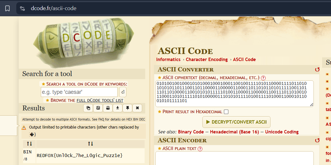
The binary sequence had 249 outputs of 0s and 1s. Upon reviewing the pattern, I suspected it was an encoded message. To decode it, I used dcode.fr to convert the binary string into ASCII text. The decoded text revealed the flag.
Finding the Flag
After converting the binary output to ASCII, I successfully extracted the flag:
REDFOX{Unl0ck_7he_L0gic_Puzz1e}
Tools & Resources Used
Claude AI (for circuit analysis)
Python (to apply Boolean logic on the input dataset)
dcode.fr (for binary-to-ASCII conversion)
Lessons Learned / Takeaways
Circuit Analysis: Using AI tools can significantly speed up the process of understanding complex circuit behavior.
Boolean Logic: Breaking down the circuit into a logical expression helped determine the output efficiently.
Binary Encoding: Recognizing binary output as potential ASCII characters was key to extracting the flag.
Rabbit Holes / Dead Ends
Initially, I considered manually tracing the circuit behavior, but it proved time-consuming and complex.
I attempted decoding the binary using different encoding schemes before realizing it was ASCII-encoded.
This challenge reinforced the importance of logical deduction and efficient problem-solving techniques in hardware-based CTF challenges.
Subscribe to my newsletter
Read articles from Nayanesh directly inside your inbox. Subscribe to the newsletter, and don't miss out.
Written by

