Chipsets
 Megha Prabhakar
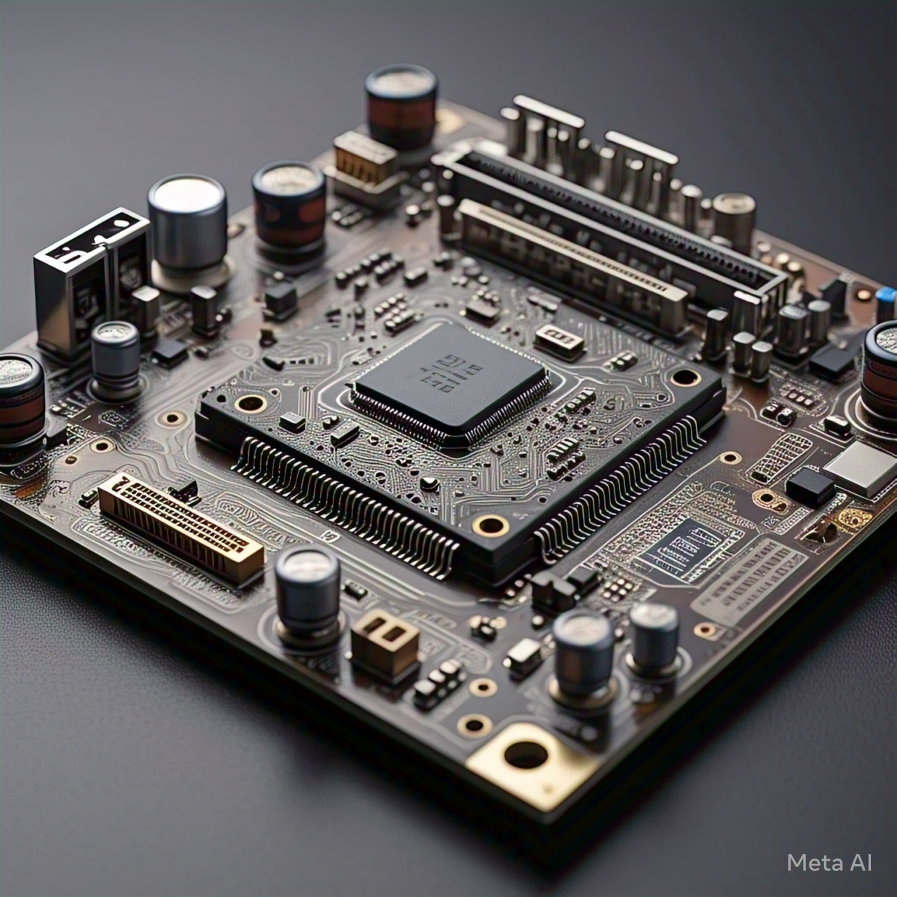
Chipset is a collection of electronic components on a motherboard that manages data flow between the computer’s components. It acts as a bridge, connecting the central processing unit (CPU) to other components such as memory, storage, and peripherals.
Functions
Memory Management: Controls access to system memory (RAM).
Storage Management: Manages data transfer between storage devices (HDD, SSD, etc.).
Peripheral Management: Connects peripherals (keyboard, mouse, USB devices, etc.).
Graphics Management: Controls graphics processing units (GPUs).
Audio Management: Manages audio signals.
Networking Management: Handles networking tasks (Ethernet, Wi-Fi, etc.).
Types of chipset
Here are the types of chipsets:
Northbridge Chipset
Controls Communication: Between CPU, memory, and graphics card.
Memory Controller: Manages memory access and control.
Graphics Controller: Manages graphics processing and control.
Southbridge Chipset
Controls Communication: Between CPU, peripherals, and I/O devices.
I/O Controller: Manages input/output operations.
Peripheral Controller: Manages peripheral devices such as USB, SATA, and PCIe.
Single-Chip Chipset or Platform Controller Hub (PCH)
Combines Northbridge and Southbridge: Into a single chip.
Reduced Power Consumption: Lower power consumption due to reduced chip count.
Improved Performance: Faster communication between CPU, memory, and peripherals.
Combines Northbridge and Southbridge: With additional features.
Improved Performance: Faster communication between CPU, memory, and peripherals.
Buses
In computer architecture, a bus (short for "omnibus") is a communication pathway that allows different components of a computer system to exchange data, instructions, and control signals. It's a shared pathway that enables multiple devices to communicate with each other.
Types of Buses:
Address Bus: Carries memory addresses from the CPU to memory devices.
Data Bus: Transfers data between devices, such as between the CPU and memory.
Control Bus: Carries control signals, such as read/write signals, between devices.
System bus architecture
System Bus Architecture (SBA) is a design approach used in computer systems where multiple components, such as the CPU, memory, and peripherals, share a common communication pathway called the system bus. This architecture enables the transfer of data, instructions, and control signals between components.
Components of System Bus Architecture:
CPU (Central Processing Unit): Executes instructions and controls data transfer.
Memory: Stores data and instructions.
Peripherals: Devices such as keyboards, displays, and storage devices.
System Bus: A shared communication pathway connecting components.
Types of System Bus Architecture:
Single Bus Architecture: All components share a single bus.
Multiple Bus Architecture: Multiple buses connect different components.
Hierarchical Bus Architecture: Buses are organized in a hierarchical structure.
Importance of POST
POST (Power-On Self-Test) is a diagnostic test that a computer's BIOS (Basic Input/Output System) or UEFI (Unified Extensible Firmware Interface) runs when the computer is powered on. The importance of POST lies in its ability to:
Ensure Hardware Functionality
Verify CPU and Memory: POST checks the CPU and memory for proper functioning.
Detect Hardware Issues: POST identifies issues with hardware components, such as the keyboard, mouse, and storage devices.
Configure Hardware: POST configures hardware components, such as setting the CPU clock speed and memory timings.
Identify System Errors
Display Error Messages: POST displays error messages or beep codes to indicate hardware issues.
Provide Diagnostic Information: POST provides diagnostic information to help troubleshoot system errors.
Enhance System Security
Authenticate Boot Process: POST authenticates the boot process to prevent unauthorized access.
Verify Firmware Integrity: POST verifies the integrity of the firmware to prevent malicious code execution.
Improve System Reliability
Detect and Recover from Errors: POST detects and recovers from errors, such as memory errors or disk failures.
Prevent System Crashes: POST prevents system crashes by detecting and resolving hardware issues.
Facilitate Troubleshooting
Provide Diagnostic Tools: POST provides diagnostic tools, such as BIOS setup and diagnostic menus.
Simplify Troubleshooting: POST simplifies troubleshooting by identifying hardware issues and providing diagnostic information.
UEFI
UEFI (Unified Extensible Firmware Interface) is a firmware interface that connects a computer's operating system to its hardware. It is a replacement for the traditional BIOS (Basic Input/Output System) and provides a more modern, flexible, and secure way to interact with the computer's hardware.
UEFI vs. BIOS:
Architecture: UEFI has a more modern and modular architecture than BIOS.
Security: UEFI provides better security features, including secure boot and networking support.
Flexibility: UEFI is more flexible and customizable than BIOS.
Hardware Support: UEFI provides better support for modern hardware than BIOS.
Why is it required
UEFI is required for several reasons:
UEFI provides a secure boot mechanism that ensures the computer boots only with authorized software, preventing malware and unauthorized access.
UEFI supports fast boot, which allows the computer to boot quickly and efficiently.
UEFI provides better support for modern hardware, including solid-state drives, USB 3.0, and SATA 6Gb/s.
UEFI provides compatibility with Modern Operating Systems like Windows, Linux, macOS
Possible configurations through UEFI
Here are some possible configurations that can be made through UEFI:
Boot Options
Boot Order: Set the order in which devices are checked for bootable operating systems.
Boot Device: Select the device to boot from, such as a hard drive, solid-state drive, or USB drive.
Secure Boot: Enable or disable Secure Boot, which ensures that only authorized operating systems can boot.
Hardware Configuration
CPU Configuration: Adjust CPU settings, such as hyper-threading, turbo boost, and CPU multiplier.
Memory Configuration: Configure memory settings, such as memory timing, voltage, and XMP (Extreme Memory Profile) settings.
Storage Configuration: Configure storage settings, such as SATA ports, PCIe slots, and NVMe settings.
Security Configuration
Password Configuration: Set passwords for UEFI settings and boot options.
TPM (Trusted Platform Module) Configuration: Enable or disable TPM, which provides hardware-based security features.
Secure Boot Keys: Manage Secure Boot keys, which ensure that only authorized operating systems can boot.
Power Configuration
Power Settings: Adjust power settings, such as sleep mode, hibernation, and wake-on-LAN.
Fan Configuration: Configure fan settings, such as fan speed and temperature thresholds.
Power Phase Configuration: Adjust power phase settings, which control the flow of power to the CPU and other components.
Advanced Configuration
PCIe Configuration: Configure PCIe settings, such as PCIe lanes, bandwidth, and priority.
USB Configuration: Configure USB settings, such as USB ports, speed, and power delivery.
Network Configuration: Configure network settings, such as LAN, Wi-Fi, and Bluetooth.
Save and Exit
Save Changes: Save changes made to UEFI settings.
Discard Changes: Discard changes made to UEFI settings.
Exit UEFI: Exit the UEFI settings menu and return to the boot process.
IDE ports
IDE (Integrated Drive Electronics) ports are a type of interface used to connect storage devices, such as hard drives, CD/DVD drives, and tape drives, to a computer's motherboard. IDE ports were widely used in older computers, but have largely been replaced by newer interfaces like SATA and PCIe.

Types of IDE Ports:
IDE (ATA-2): The original IDE port, supporting data transfer rates up to 16.6 MB/s.
Fast IDE (ATA-3): An updated IDE port, supporting data transfer rates up to 33.3 MB/s.
Ultra IDE (ATA-4): A further updated IDE port, supporting data transfer rates up to 66.6 MB/s.
Ultra DMA IDE (ATA-5): The final version of the IDE port, supporting data transfer rates up to 100 MB/s.
Methods of adding SCSI drives
SCSI (Small Computer System Interface) is a interface standard for connecting peripherals, such as hard drives, tape drives, and CD/DVD drives, to a computer.
Here is the picture of different SCSI Connectors:

Here are the methods of adding SCSI drives in a computer:
Internal SCSI Connection
SCSI Controller Card: Install a SCSI controller card in a PCI slot on the motherboard.
SCSI Cable: Connect the SCSI cable to the SCSI controller card and the SCSI drive.
SCSI ID: Set the SCSI ID on the drive to a unique value to avoid conflicts with other devices.
External SCSI Connection
SCSI Host Adapter: Install a SCSI host adapter in a PCI slot on the motherboard.
SCSI Cable: Connect the SCSI cable to the SCSI host adapter and the external SCSI drive.
SCSI ID: Set the SCSI ID on the drive to a unique value to avoid conflicts with other devices.
Hot-Swappable SCSI Connection
SCSI Hot-Swap Bay: Install a SCSI hot-swap bay in a drive bay on the computer.
SCSI Drive: Insert the SCSI drive into the hot-swap bay.
SCSI ID: Set the SCSI ID on the drive to a unique value to avoid conflicts with other devices.
RAID SCSI Connection
SCSI RAID Controller: Install a SCSI RAID controller in a PCI slot on the motherboard.
SCSI Cables: Connect the SCSI cables to the SCSI RAID controller and the SCSI drives.
SCSI ID: Set the SCSI ID on each drive to a unique value to avoid conflicts with other devices.
Fibre Channel SCSI Connection
Fibre Channel Host Adapter: Install a Fibre Channel host adapter in a PCI slot on the motherboard.
Fibre Channel Cable: Connect the Fibre Channel cable to the Fibre Channel host adapter and the Fibre Channel switch.
SCSI ID: Set the SCSI ID on each drive to a unique value to avoid conflicts with other devices.
CMOS battery
A CMOS (Complementary Metal-Oxide-Semiconductor) battery is a small battery used in computers to power the CMOS chip, which stores the computer's configuration settings, such as:
CMOS Settings:
Date and Time: Stores the current date and time.
Boot Order: Specifies the order in which the computer boots from different devices.
Hardware Settings: Stores settings for hardware components, such as the hard drive, floppy drive, and CD/DVD drive.
BIOS Settings: Stores settings for the Basic Input/Output System (BIOS), such as boot passwords and security settings.
Types of CMOS Batteries:
CR2032 Battery: A common type of CMOS battery used in most computers.
CR2016 Battery: Used in some older computers or specialized systems.
CMOS BATTERY:

Why we need CMOS battery?
Purpose of CMOS Battery:
Power CMOS Chip: Provides power to the CMOS chip when the computer is turned off.
Retain Settings: Ensures that the CMOS settings are retained even when the computer is powered off.
Specifications
Here are the specifications of a typical CMOS battery used in computers:
Physical Specifications:
Type: CR2032 or CR2016
Shape: Round, button-cell shape
Diameter: 20mm (CR2032) or 16mm (CR2016)
Thickness: 3.2mm (CR2032) or 1.6mm (CR2016)
Weight: Approximately 2-3 grams
Electrical Specifications:
Voltage: 3.0V (CR2032) or 3.0V (CR2016)
Capacity: 220-240mAh (CR2032) or 90-100mAh (CR2016)
Current: 0.1-0.2mA (typical)
Internal Resistance: 10-20 ohms
Self-Discharge: 2-5% per year
Operating Specifications:
Operating Temperature: 0°C to 60°C (32°F to 140°F)
Storage Temperature: -20°C to 70°C (-4°F to 158°F)
Humidity: 40% to 80% relative humidity
Lifespan:
Typical Lifespan: 5-10 years, depending on usage and storage conditions
Shelf Life: Up to 10 years, depending on storage conditions
Replacement:
Replacement Interval: Typically every 5-10 years, or when the battery is depleted
Replacement Procedure: Shut down the computer, remove the battery, and replace it with a new one
Impact of removing the battery from motherboard
Removing the CMOS battery from the motherboard can have several impacts on the computer:
Immediate Impacts:
Loss of CMOS Settings: The computer will lose its CMOS settings, including the date, time, and boot order.
BIOS Reset: The BIOS will reset to its default settings, which may cause issues with hardware detection and configuration.
Boot Issues: The computer may not boot properly or may display error messages.
Short-Term Impacts:
Date and Time Issues: The computer will display an incorrect date and time, which can cause issues with software and system functionality.
Hardware Detection Issues: The computer may not detect hardware components properly, leading to issues with device installation and configuration.
System Instability: The computer may experience system instability, crashes, or freezes due to incorrect BIOS settings.
Long-Term Impacts:
Corruption of System Files: If the computer is booted without a CMOS battery, system files may become corrupted, leading to system instability or failure.
Hardware Damage: In rare cases, removing the CMOS battery can cause hardware damage, such as damage to the motherboard or other components.
Data Loss: If the computer is not properly shut down before removing the CMOS battery, data may be lost or corrupted.
Conclusion
In conclusion, a chipset is a crucial component of a computer's motherboard, acting as a bridge between the CPU, memory, and other hardware components. It manages data transfer, controls hardware functions, and provides connectivity options. Understanding the chipset's role, types, and features is essential for building, upgrading, or troubleshooting a computer. By selecting the right chipset, users can optimize their system's performance, compatibility, and scalability.
Subscribe to my newsletter
Read articles from Megha Prabhakar directly inside your inbox. Subscribe to the newsletter, and don't miss out.
Written by