Mobile Robot Concept Design Development
 Nikita Bragin
In May Robonine completed a first variation of the full robot design. We want to show, step by step, what we started from and what we finally achieved.
Initial Requirements
A 3D design concept needs to be created with consideration for the technical specifications of the structure.
The model should be showcased in an environment – indoors, controlled by a person using a VR Oculus Quest 3.
Source files must be provided.
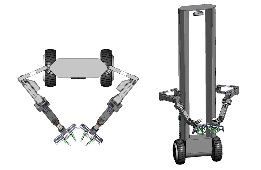
Initial concept. Design provided by our engineer
External Parameters
Matte black color. Alternative color schemes may be considered: white, yellow.
Frame dimensions: 350 mm to 400 mm × (1300 mm to 1400 mm, including wheel height).
Operating format similar to a Segway.
The view of the upper П-shaped frame from the front and back should be identical.
A depth camera and LiDAR should be installed on the upper frame.
LED strips should be installed on the side frames.
LED strips should also be installed on the lower platform.
Depth cameras (similar to Intel RealSense D405) should be mounted on the manipulators.
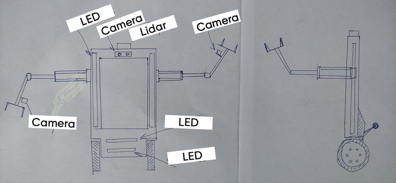
Sketch showing position of detectors
Balancing Mechanism
The tail will be in a lowered position all the time and will have a straight shape resembling the letter П, with a roller at each end. The rollers are non-driven.
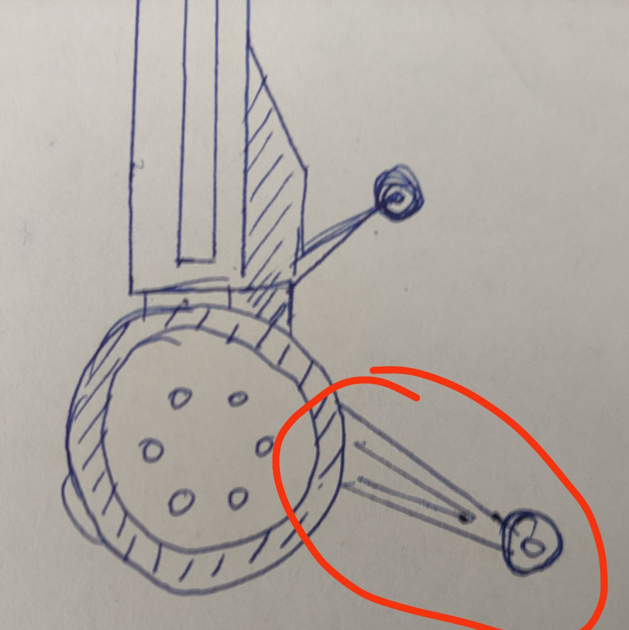
Balancing mechanism – Profile view
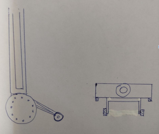
Balancing mechanism
Wheels
Swiveling wheels, like in the image: 3-inch Small Industrial Caster Wheels – Alibaba
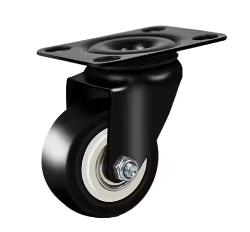
Robot back wheels
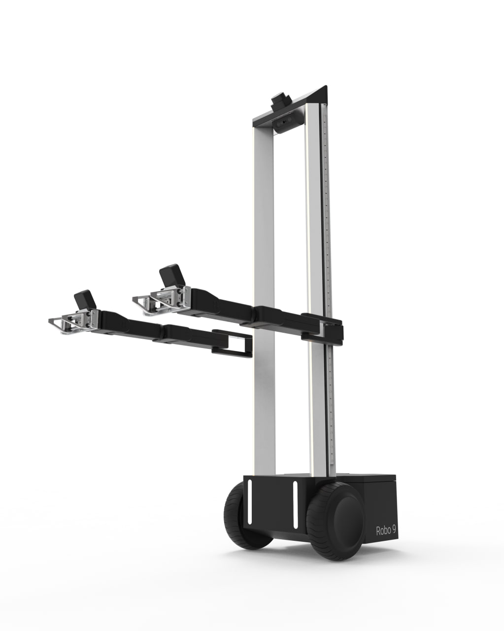
Manipulators
The manipulators extend to the full height of the pole.
Height: 1300 mm
Length: 650 mm
The appendage on the second joint should be adjusted. The engineer will determine whether to remove or shift the structure inward.
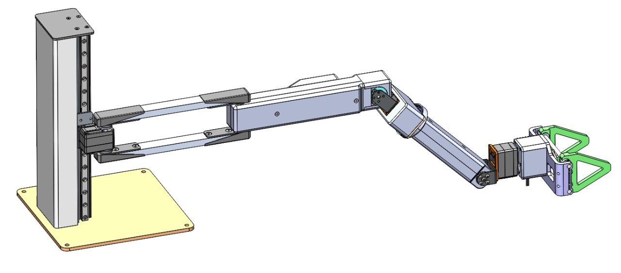
Robot arm
Design of the Gripper
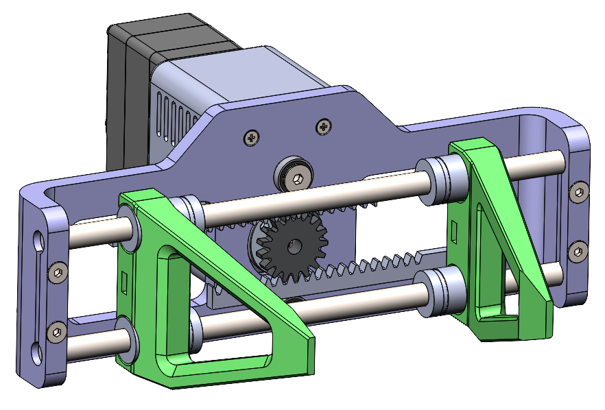
Parallel gripper design
Position of Manipulator Poles
The poles should be turned at a 45-degree angle to ensure maximum reach.
This angle provides as much working space as possible for the manipulators.
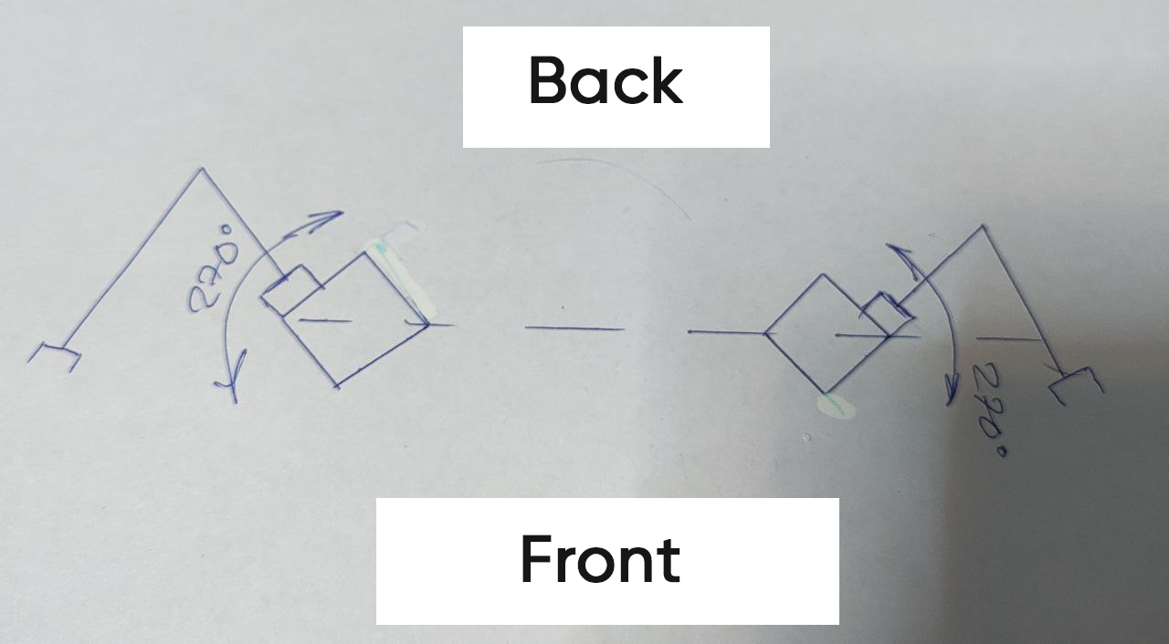
Main frame poles angle
Top Sensors
The depth camera should be able to rotate back and forth.
Initially, we planned to use 3D LiDARs, so one was placed on top.
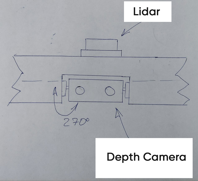
Top sensors
Lower Wheel Motors
Size: 8.5 inches
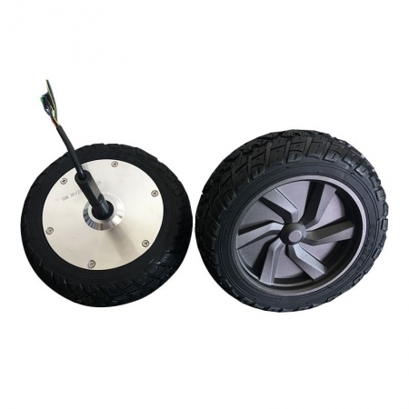
Front electric motor wheels
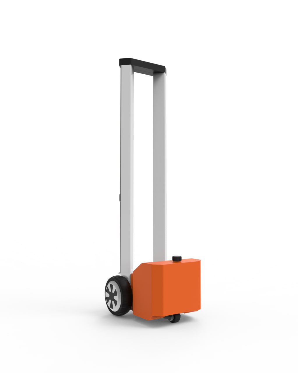
First Version of the Robot's Main Frame
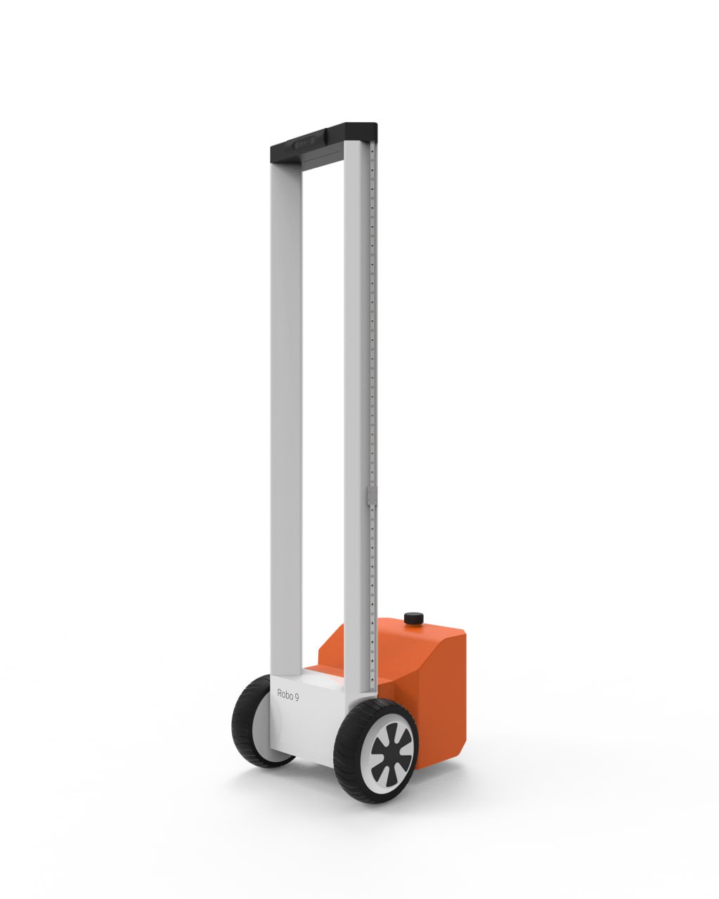
Front view
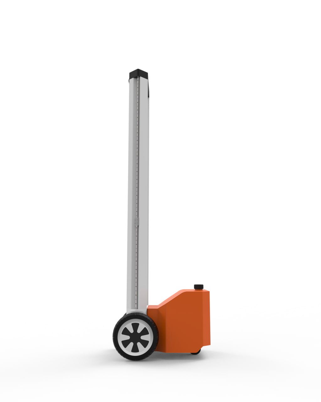
Profile view
Back view
In this version:
We decided to use a heavy back instead of an adaptive tail. Initially, we considered a water tank to provide ~20kg weight to compensate for the forward tipping moment when the arms are fully extended.
The designer used orange color to make the robot visible from a distance.
Second Version of the Robot's Main Frame
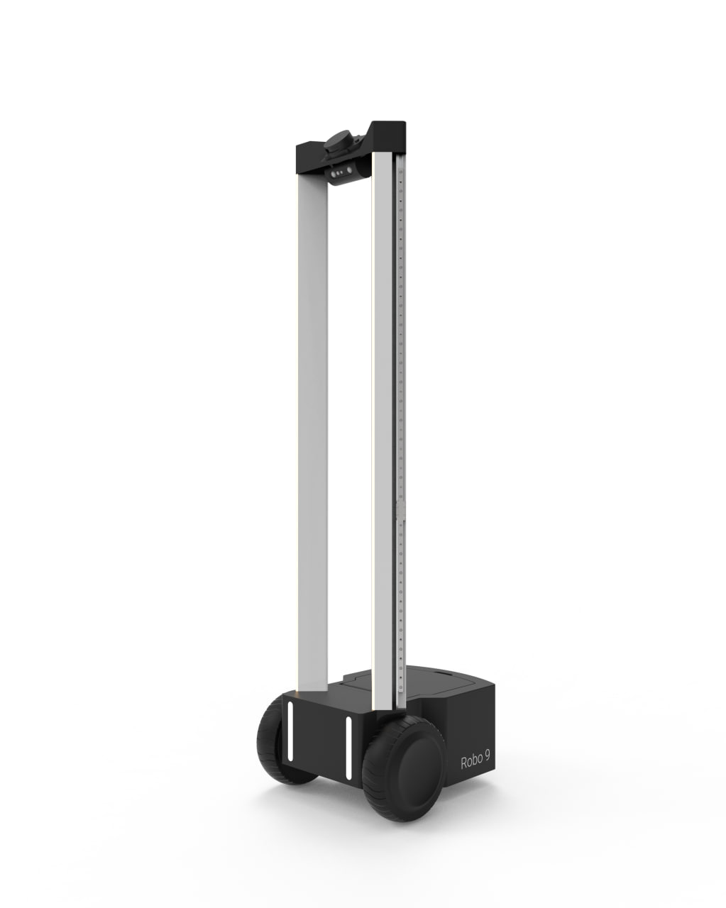
Second version – Front view
Second version – Back view
Updates:
Switched to black color, as tough engineering plastics are typically black.
Flat surface on the back for users to place items.
Instead of a water tank, we now use heavy-duty batteries to compensate for forward tipping.
Front lights added on the mobile base.
LiDAR and depth camera added at the top of the frame.
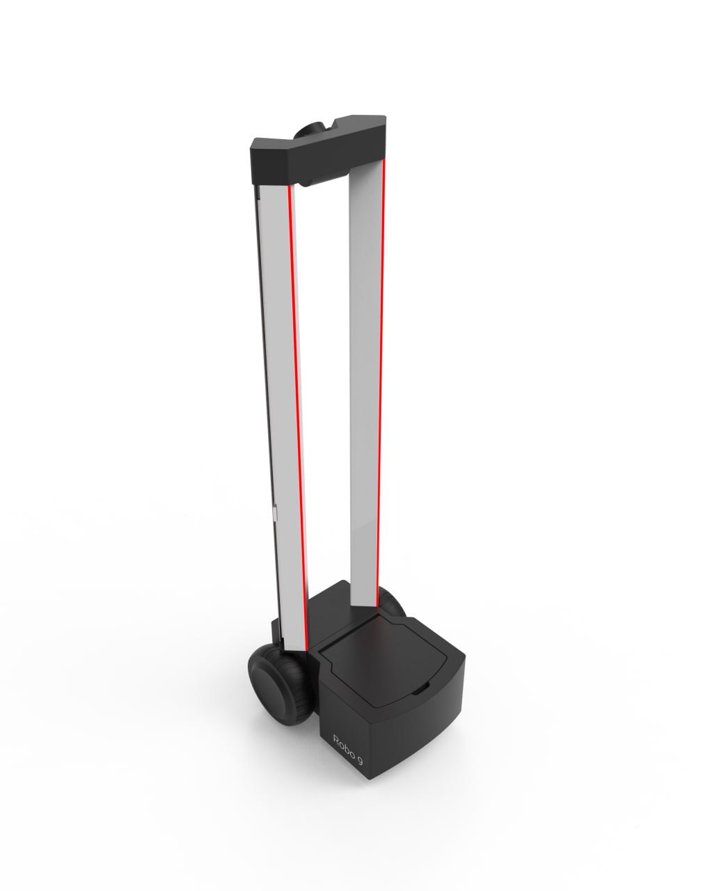
Latest Version of the Concept Design (Not Final)
Robot V0 Design Concept – Front view
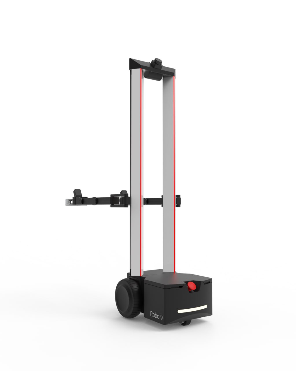
Robot V0 Design Concept – Back view
Designer added 2 manipulators.
Added back light.
Emergency stop button to prevent any extreme behavior. Like on a video:

- Second LiDAR added.
Notes
Final design will differ from the current version:
We are currently working on compensating for motor backlash using a dual-servo design. The final arms will have a different design.
Instead of 3D LiDARs, we will likely use a combination of 2D/1D LiDARs and ultrasonic distance sensors.
Subscribe to my newsletter
Read articles from Nikita Bragin directly inside your inbox. Subscribe to the newsletter, and don't miss out.
Written by