How to Design a Pasta Dough Roller Using 3D CAD Software
 Juliana Misiko
How to Design a Pasta Dough Roller Using 3D CAD Software
Fresh pasta is a joy to make, but rolling out the dough evenly can be a challenge without the right tools. What if you could design your own custom pasta dough roller tailored to your needs? In this guide, we’ll show you how to create one from scratch using SelfCAD, a user-friendly 3D modeling platform perfect for DIY kitchen tools. Whether you're a home chef exploring 3D printing or a maker looking for your next functional project, this step-by-step tutorial will help you model a pasta roller that's practical, printable, and ready for your next culinary adventure
To access the interactive tutorial to this article, check out; https://www.selfcad.com/tutorials/2a213y576r2f4v6h3h28bt6m4n1z1k1n4f5r
Once you’ve launched the editor;
From the 3D Shapes category on the toolbar choose cube; Set height to 125, depth to 20
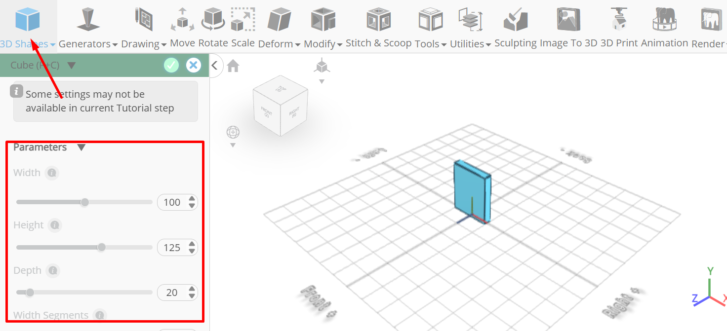
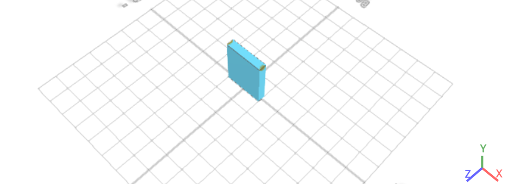
Tick the checkmark finalize cube
Click to activate edge selection; Click on highlighted region to select it
From the modify category on the toolbar choose fillet; Set intensity to 30, level to 10
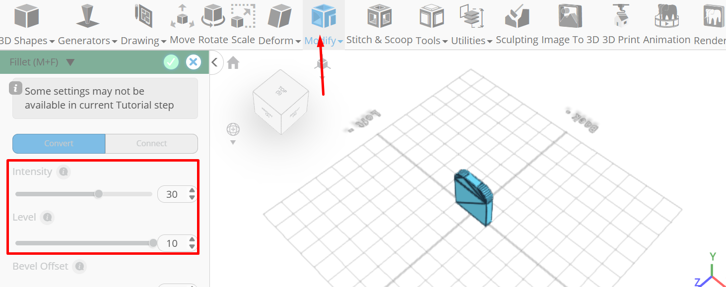
Tick the checkmark to finalize fillet
Click copy button to copy selected objects; Click scale on the toolbar; Set y to 86.24 using highlighted gizmo
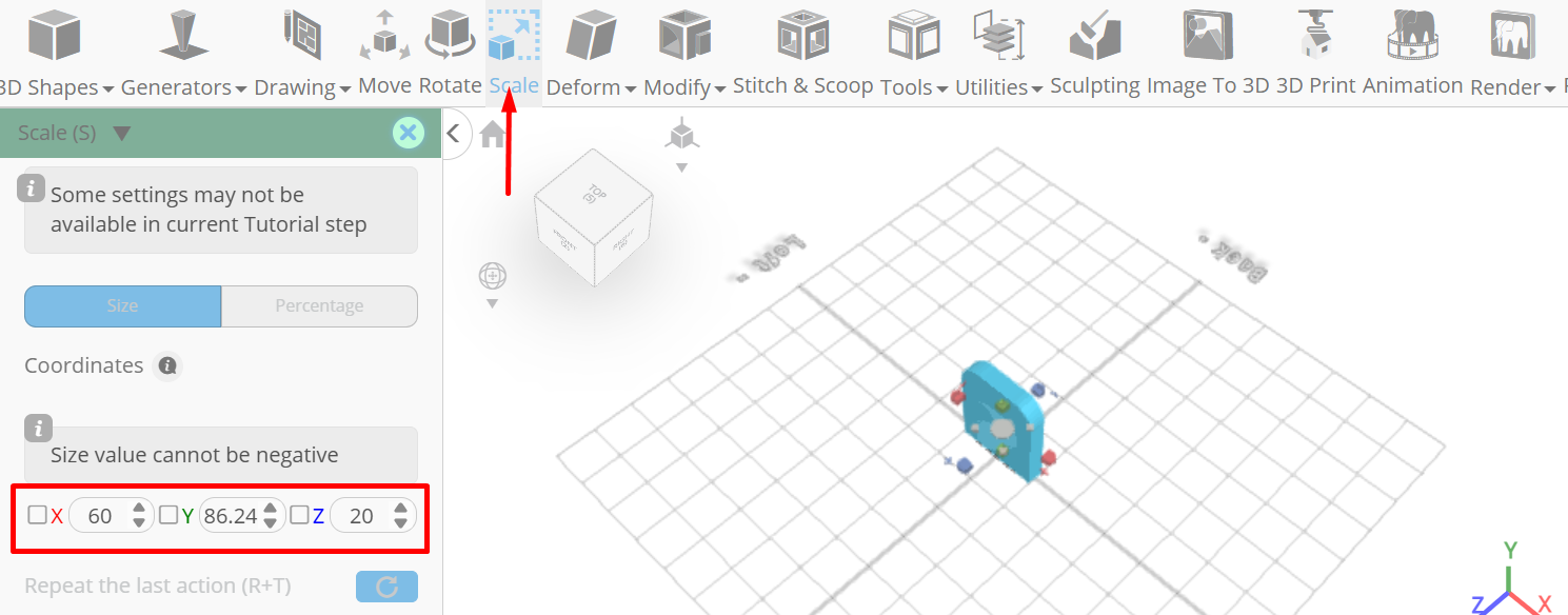
Click ‘x’ to close transformation panel
Click highlighted part on selection cube to turn off region selection, Click on mesh 4 to select it
Click stitch & scoop on the toolbar; from the tool panel choose difference, Choose mesh 4(1) to subtract.
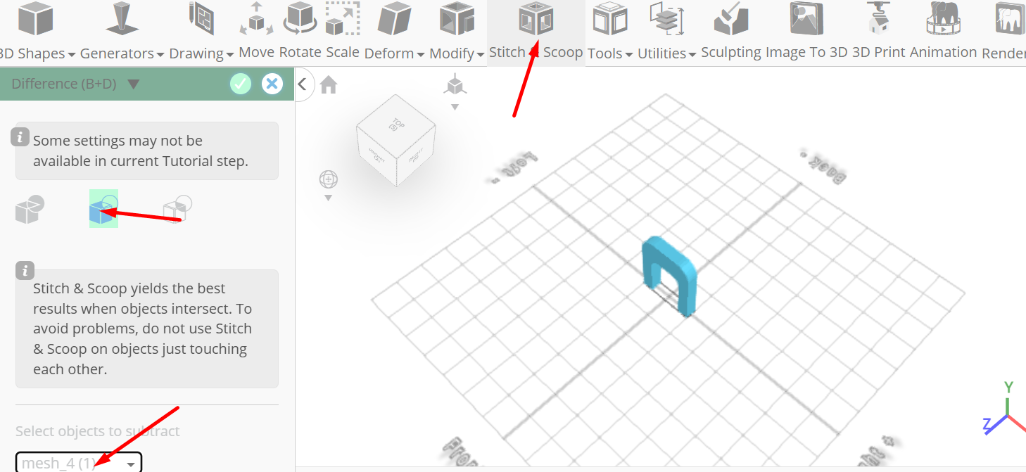
Tick the checkmark to finalize difference
Click copy button to copy selected objects; Click move on the toolbar; Set z to -110
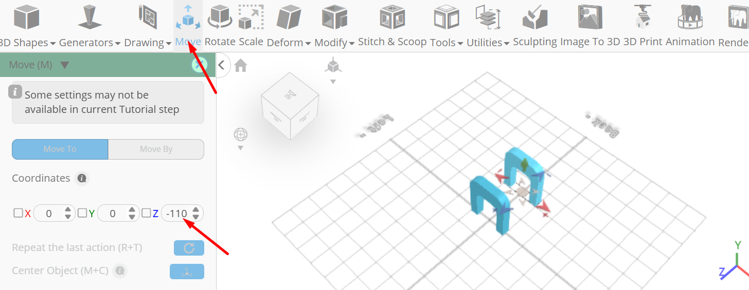
Click ‘x’ to close transformation panel
From the 3D Shapes category on the toolbar choose cylinder; Set top radius to 15, Bottom radius to 15, height to 85, vertical segments to 128, position x to 20, position y to 87, position z to -55, rotation x to 90.
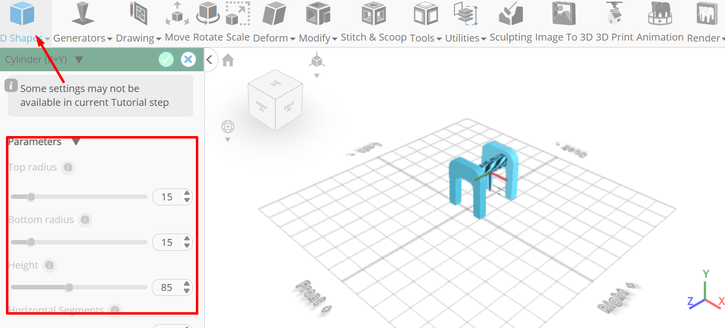
Tick the checkmark to finalize cylinder
From the 3D Shapes category on the toolbar choose cylinder; Set top radius to 5, Bottom radius to 5, height to 10, vertical segments to 128, position x to 20, position y to 97, position z to -9, rotation x to 90.
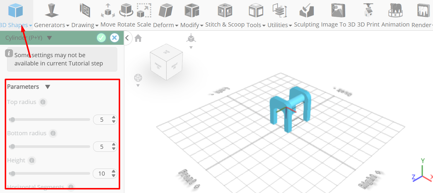
Tick the checkmark to finalize cylinder
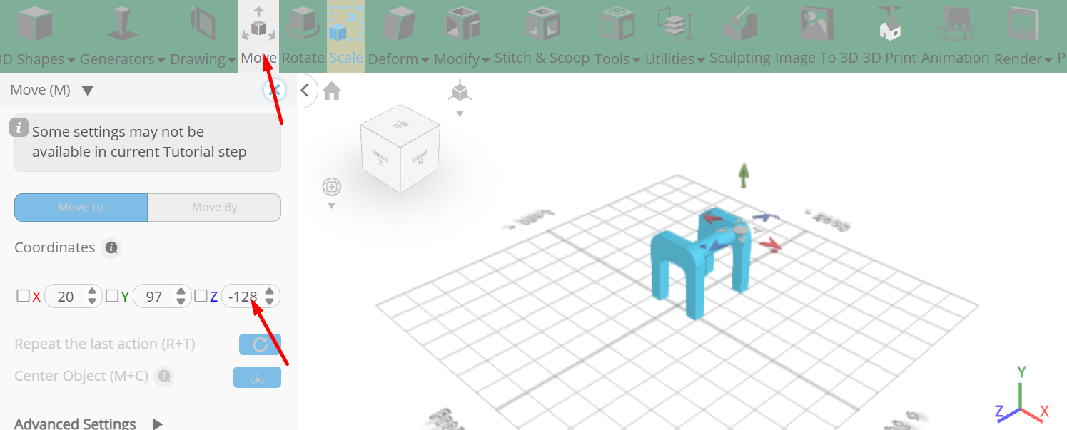
Click copy button to copy selected objects; Click move on the toolbar; Set z to -128
Click scale on the toolbar; Set z to 36 using highlighted gizmo
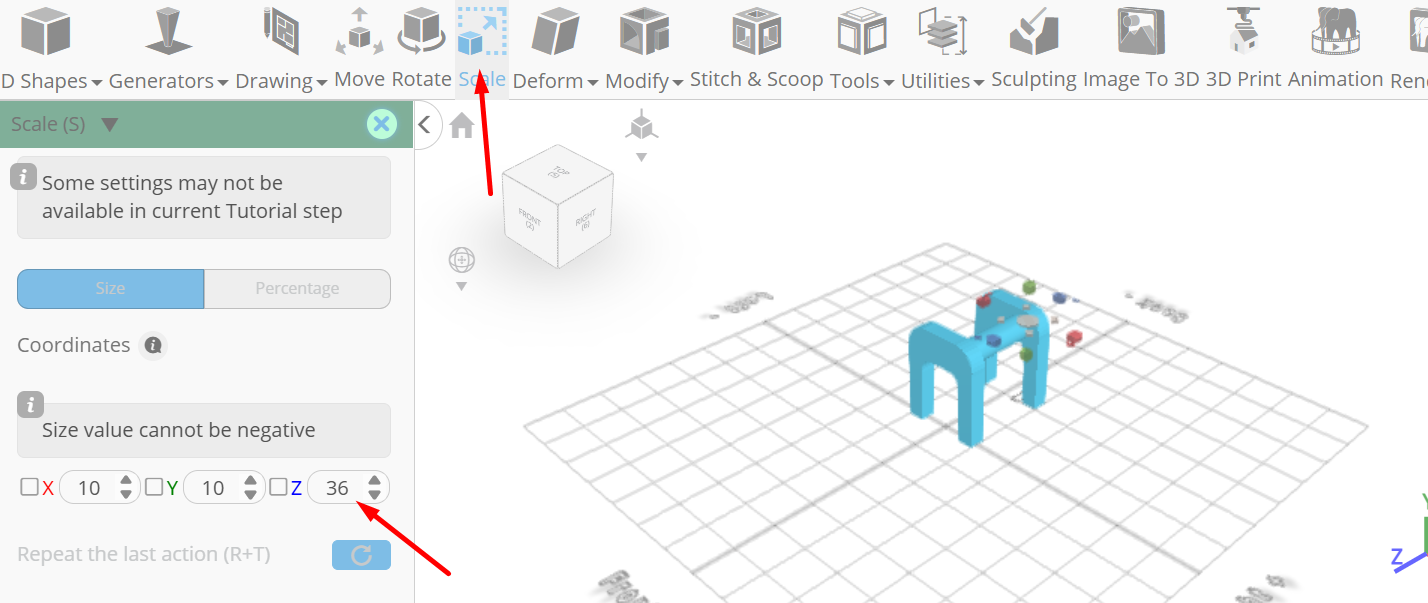
Click ‘x’ to close transformation panel
Click on mesh 12, mesh 8 to select it
Click copy button to copy selected objects; Click move on the toolbar; Set x to -11
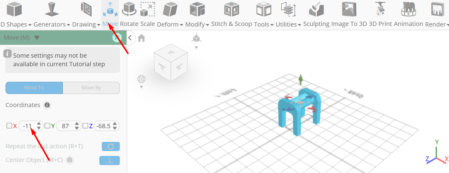
Click ‘x’ to close transformation panel
From the generators category on the toolbar choose gear generator; Set module to 1, position x to 20, position y to 85, position z to -127, rotation x to 90
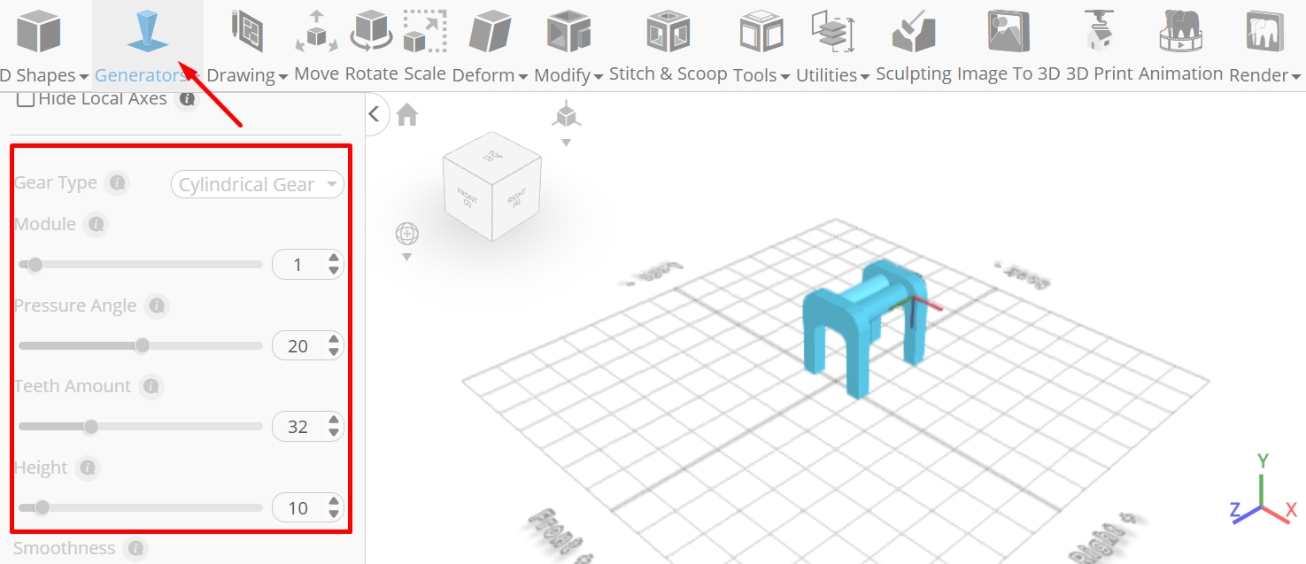
Tick the checkmark to finalize gear generator
Click scale on the toolbar; Set x to 32, y to 32
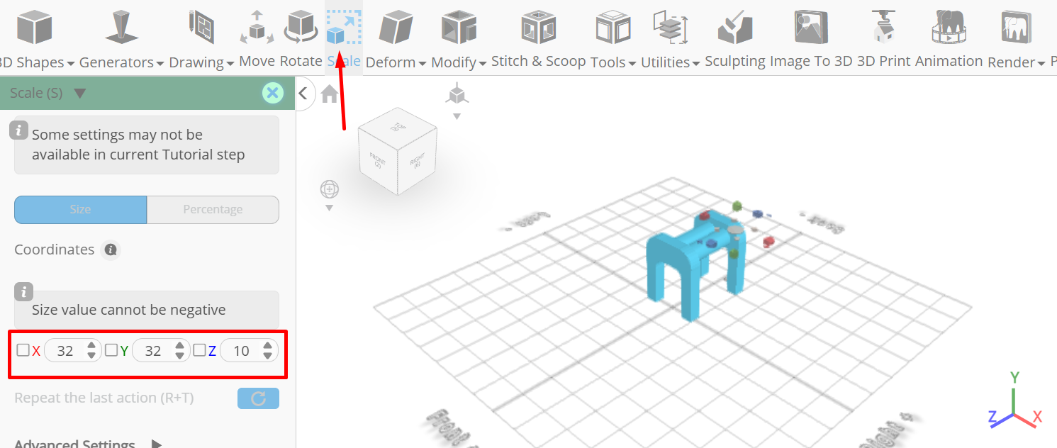
Click ‘x’ to close transformation panel
From the 3D Shapes category on the toolbar choose cylinder; Set top radius to 10, Bottom radius to 10, height to 5, vertical segments to 128, position x to -11, position y to 92, position z to -135, rotation x to 90.
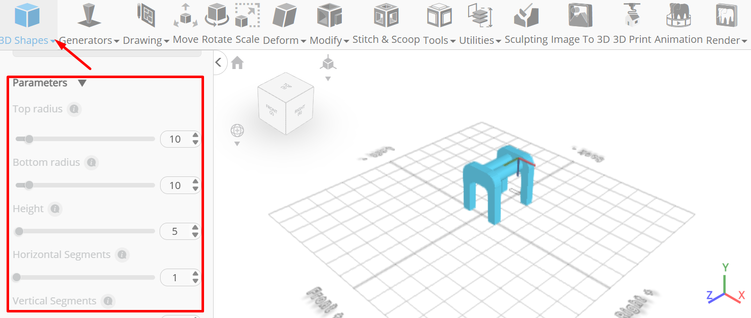
Tick the checkmark to finalize cylinder
From the right panel choose cube selection; Set units to percentage, right to 50
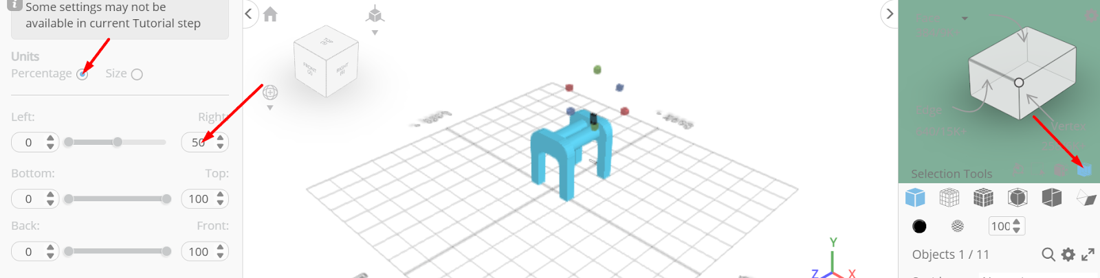
Tick the checkmark to finalize cube selection
Click move on the toolbar; Set x to -70
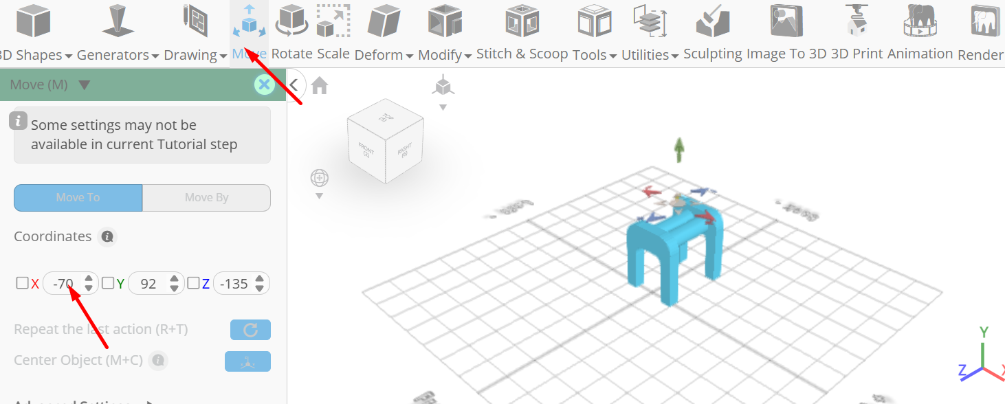
Click ‘x’ to close transformation panel
Click on highlighted region to deselect it
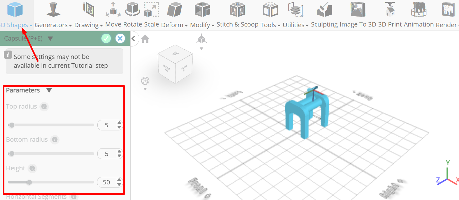
From the 3D Shapes category on the toolbar choose capsule; Set top radius to 5, bottom radius to 5, height to 50, position x to -65, position y to 97, position z to -158, rotation x to 90
Click on mesh 12, 12(1,2,3) to select. Click on mesh 20 to deselect, From the edit menu on the top toolbar choose group
Click on difference 1(1), difference 1 to select; Click stitch & scoop on the toolbar; from the tool panel choose difference, Choose group 1 subtract and set keep subtracted object to true
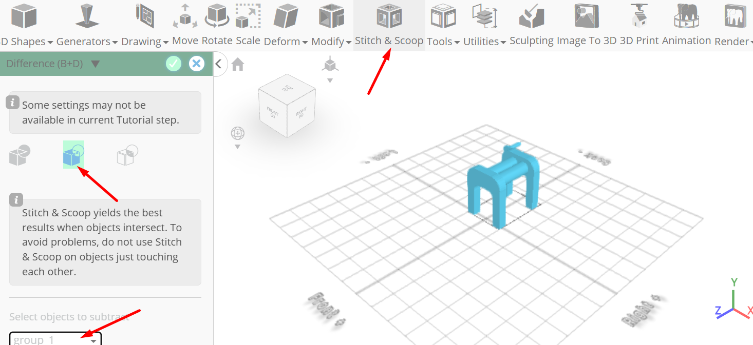
Tick the checkmark to finalize difference
Click on difference 2 to deselect; From the edit menu on the top toolbar choose ungroup
Click on mesh 8(1), 16, 20, gear 1(1), to select. Click on mesh 12, 12(1) to deselect; Click stitch & scoop on the toolbar; From the tool panel choose union.
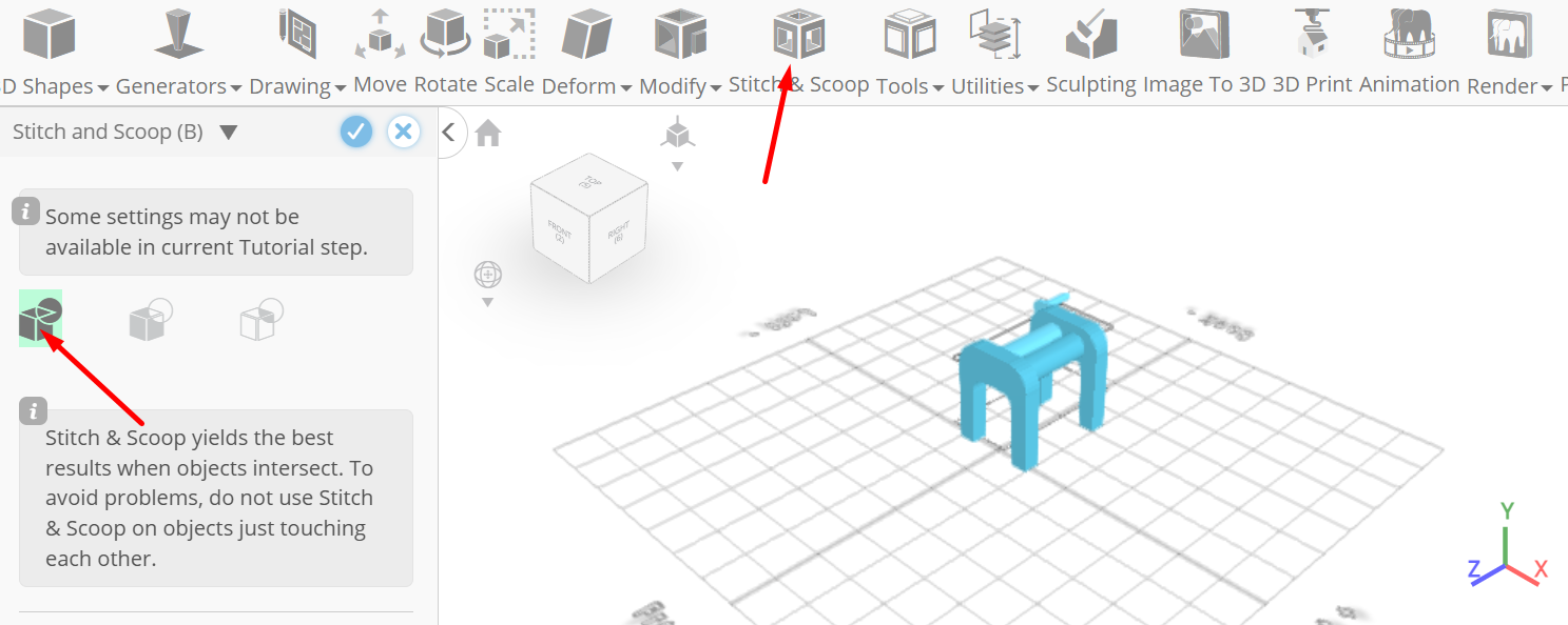
Tick the checkmark to finalize union
Click on mesh 12, 8, 12(1), gear 1 to select. Click on union 1 to deselect
Click stitch & scoop on the toolbar; From the tool panel choose union.
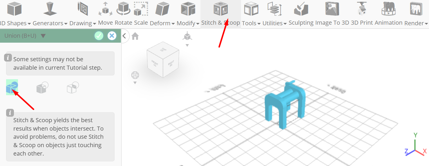
Tick the checkmark to finalize union
As you continue honing your design skills, remember that SelfCAD offers a wealth of resources to support your learning journey. To deepen your understanding and explore more advanced features, consider checking out the interactive tutorials (https://www.selfcad.com/tutorials) available on the SelfCAD website. The tutorials page provides a treasure trove of guides, tips, and tricks that cater to designers of all levels.
More structured learning experience can also be accessed at the SelfCAD Academy (https://www.selfcad.com/academy/curriculum/), https://www.youtube.com/@3dmodeling101, and 3D Modeling 101 series (https://www.youtube.com/playlist?list=PL74nFNT8yS9DcE1UlUUdiR1wFGv9DDfTB). This comprehensive resource offers in-depth courses taught by industry experts, allowing you to master the intricacies of SelfCAD at your own pace.
Subscribe to my newsletter
Read articles from Juliana Misiko directly inside your inbox. Subscribe to the newsletter, and don't miss out.
Written by