ScapyTapper: Building a Simple Packet Sniffer to Understand Network Analysis from Scratch
 Subhash Kashyap
This past summer, I dove deep into the world of network analysis. I’ve always been curious about how the Internet works — beyond just using it. So instead of reading endless theory, I took a hands-on approach to truly understand its core.
That’s how ScapyTapper was born — a simple Python-based packet sniffer I built using the Scapy library. This project became my gateway into the fundamentals of networking: the OSI model, TCP/IP stack, ARP, packets, headers — and how real data moves from one device to another.
In this article, I’ll walk you through my journey — from studying protocol layers to capturing live packets — and show how building a packet sniffer from scratch can teach you more than what your typical textbook ever could.
What is packet travel? What are the OSI and TCP/IP models? The journey of building “ScapyTapper” is covered in this article.
Check out the source code: https://github.com/Subkash2206/ScapyTapper
Table of Contents
This article covers:
Fundamentals of Network Communication
The OSI Model (7 Layers)
The TCP/IP Model and Its Relevance
What is a Packet? (Anatomy & Headers)
Introduction to Scapy
Building ScapyTapper: Step-by-Step
Key Features Implemented
Conclusion + GitHub Repo
Introduction to Network Analysis
Network analysis is quite a complex subject.
Before starting a network analysis project, it is of utmost importance to have a good understanding of the fundamentals.
This includes:
network structure
protocols
traffic flow.
If you don’t have a good understanding of these essential concepts, the output from your packet sniffer can be overwhelming and rather difficult to understand and analyze, which could potentially lead you to make mistakes in interpreting the data.
Understanding basic network analysis will allow us to decode protocol layers like TCP/IP and HTTP, identify payloads, and provide a basic idea of formats such as pcap and its uses.
So how does Computer to Computer communication take place?
This is quite a perplexing topic which can best be understood via the OSI model(open systems interconnect), which goes in depth in terms of the explanation of all the individual functions involved for this communication to take place.
The OSI model is divided into 7 different and unique layers:
7. Application
6. Presentation
5. Session
4. Transport
3. Network
2. Data Link
- Physical
For our packet sniffer project, the first 4 layers are of utmost relevance and the understanding of these core concepts are absolutely vital in working on such a project.
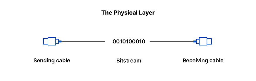
LAYER 1: PHYSICAL
The first layer of the OSI model is responsible for the transfer of bits (1s and 0s).
Essentially, layer 1 is anything that carries 1’s and 0’s between 2 nodes
The medium of transmission could differ, an example being ethernet wherein bits are transferred via electrical pulses whereas in the case of WIFI, the bits are transferred in the form of radio waves.
A repeater is a physical device used to repeat a signal from medium to another thereby increasing the range of the said signal.
A Hub is a multi-port repeater.
LAYER 2: DATA LINK
To put it simply, the data link layer is responsible for putting these 1’s and 0’s on the wire and subsequently pulling 1’s and 0’s from the wire when necessary.
Essentially, it receives signals from the wire and transfers signals onto the wire as well.
Layer 2 groups 1’s and 0’s together into chunks known as frames.
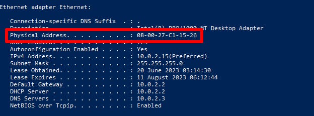
MAC(Media Access Control) Address: There exists an addressing system on Layer 2 in order to uniquely identify nodes for network interfaces, enabling communication within a local network.
This addressing system is used to:
uniquely identify devices present on a network.
ensure that the data packets are delivered to the correct destination.
This is a permanent address burnt in by the manufacturer.
The role of Layer 2 is to deliver packets from hop to hop.
A Switch is a physical device which operates on Layer 2 and responsible for facilitating communication within networks.
It’s a network device that connects devices within a local network by forwarding the data frames based on the MAC Addresses.
LAYER 3: NETWORK
The network layer which is perhaps the most important layer of them all is responsible for packet delivery from end to end.
This is done via yet another addressing scheme which effectively identifies every single node connected to the internet. This addressing scheme is known as the IP Address*(Internet Protocol)*
The IP Address of a computer/node isn’t a permanent identification of a computer unlike in the case of the MAC address.
Routers work on Layer 3 and are responsible for facilitating the communication between networks.
A router also acts as a boundary between 2 networks.
Routers are used to communicate with devices which are not present in the current network.
Difference between Layer 2 and Layer 3:
Layer 2:
Uses MAC Address
Responsible for packet delivery from hop to hop
IP header and data are encapsulated in a MAC address header, which includes the source and destination MAC address of the current “hop”, a number of which are required in the path to the final destination.
Layer 3:
Uses IP Address
Responsible for packet delivery from end to end
Source and Destination IP addresses are mentioned.
For further understanding:
Hence, the difference between “hop to hop delivery” and “end to end delivery”
LAYER 4: TRANSPORT
Take this example, you are multitasking on your computer. You have your web browser open whilst streaming music simultaneously. These applications send and receive data to and from the internet in the form of 0’s and 1’s.
We must be able to effectively distinguish as to which of the 0’s and 1’s belong to the web browser and which of them belong to the music streaming service. This is done via Layer 4.
Layer 4 utilizes an addressing scheme known as Port Numbers
These include the TCP*(transmission control protocol) and the UDP(User Datagram Protocol)*
Both of these have 2^{16} ports each.
Essentially, Layer 4 is responsible for service to service delivery.
Encapsulation and Decapsulation
Data is moved from top to bottom(7 to 1) when sending and bottom to top(1 to 7) when receiving.
Layer 4 will add a TCP header which would include a Source and Destination port
Layer 3 will add an IP header which would include a Source and Destination IP address
Layer 2 would add an Ethernet header which would include a Source and Destination MAC address
Key Players involved:
Host → any end device on the Internet (origin/final destination of the traffic)[Client and server]
Network → 2 or more connected devices
Switch → facilitates communication within networks. Acts on Layer 2.
Router → facilitates communication between networks. Operates on Layer 3.
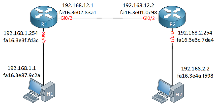
Address Resolution Protocol(ARP)
ARP bridges the MAC addresses and the IP addresses
Usually when 2 hosts are communicating, their IP addresses are known to one another. However, the MAC address isn’t known.
ARP essentially uses the known IP addresses and discovers the unknown MAC addresses.
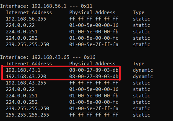
This mapping is then stored in an ARP Table which is a mapping of the IP addresses to their respective MAC addresses.
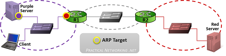
CASE 1: Client speaking to the purple server
When the client is speaking to the purple server located within the same network, it will know this information as well the purple server’s IP address.
The client will then issue an ARP request for the host’s MAC address.

CASE 2: Client speaking to the red server
When the client is speaking to the red server located outside of the scope of the local network, the packet is delivered to the nearest router(known as the default gateway).
The client will then request the Default Gateway for its MAC Address.

This occurs on the “hop-to-hop” basis
All Layer 3 devices must maintain an ARP Table.
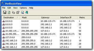
Routing Table:
The routing table is a map of all networks in existence.
It acts as the determinant factor as to what the best path is, in order to forward packets towards the destination.
Components:
Destination IP
Subnet Mask which defines the size of the network( /24)
IP of the next hop
Interface (ens33)
Route Type (Direct, static, Dynamic)
An Overview of the TCP/IP Model
While the OSI Model is a great conceptual framework for understanding network communication, the TCP/IP Model is what the Internet actually uses. It’s more practical and simplified, typically consisting of just 4 layers.
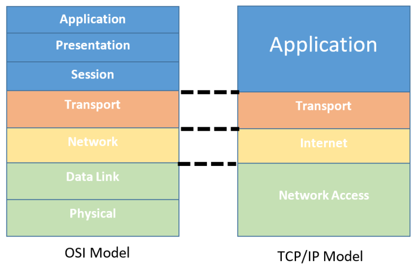
Layer-wise Breakdown
Application Layer: All high-level protocols like HTTP, DNS, FTP, etc.
Transport Layer: Manages end-to-end communication. TCP ensures reliable delivery, while UDP offers speed at the cost of reliability.
Internet Layer: Responsible for addressing and routing via IP (Internet Protocol).
Link Layer: Deals with local network communication (MAC addresses, Ethernet, Wi-Fi, etc.)
Why the TCP/IP Model Matters for Packet Capturing
When capturing IP packets, you’re essentially dealing with the Internet Layer.
When analyzing TCP flags or port numbers, you’re in the Transport Layer.
If you’re inspecting HTTP requests, you’re operating at the Application Layer.
In essence, the fundamental understanding of the TCP/IP model is absolutely essential to effectively capture and analyze these units of data known as “packets.”
If you’ve come this far into the article, you must’ve noticed that the term “packet” is thrown around quite a lot.
Now that begs the question as to what a packet actually is.
What is a Packet?
To put it simply, a packet is the fundamental unit of data that is transmitted across a network. Everything you do online — whether it’s loading a webpage, sending an email, or chatting with a friend online— involves the exchange of packets.
A packet typically consists of two parts:
Header(s): Contains metadata such as source and destination addresses, port numbers, sequence numbers, and protocol information.
Payload: The actual data being transmitted — for example, the content of an HTTP request or a DNS query.
As the data travels through the network and the various different layers, headers are added to it accordingly and this process is known as encapsulation, as mentioned earlier. The reverse process is known as decapsulation.
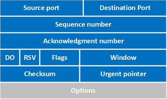
TCP Header
The TCP (Transmission Control Protocol) is one of the most widely used protocols in networking. When analyzing packets, understanding the structure of a TCP header can reveal a lot about the communication taking place.
A typical TCP header is 20 bytes long and contains the following fields:
Source Port: The port on the sender’s device
Destination Port: The port on the receiver’s device
Sequence Number: Used to keep track of data chunks in order
Acknowledgment Number: Confirms receipt of data from the other end
Data Offset: Indicates where the data begins
Flags: 6 important 1-bit flags like SYN, ACK, FIN, etc.
Window Size: Flow control mechanism to manage buffer size
Checksum: Used for error-checking the TCP header and data
Urgent Pointer: Indicates if any data is urgent (rarely used)
Options: For extended features like window scaling
Now that we’ve got the theory pat down, it’s time to get a bit more practical and actually dive into making a simple packet capture and analysis tool to better understand these highly theoretical concepts in a more practical manner.
Introduction to Packet Sniffers
What are we sniffing?
Essentially, we are creating a network tool in order to capture and analyze network traffic.
Basically, we intercept and record data packets transmitted between computers/devices on a local network.
These packet sniffers are most commonly used as troubleshooting and security analysis tools to identify network problems such as packet loss, congestion, network intrusions and so on.
The packet sniffer tool I worked on involved a broad and generalized two step process:
We capture these packets using a popular python library called“scapy” in real time as they are transmitted across the network.
We analyze these packets, and display the relevant information to the user in a human readable format
Packet sniffers can be used on both wired and wireless connections and the captures can occur in various network protocols including tcp/ip, https, ftp, and so on.
One such widely used and popular packet sniffer/network analysis tool is Wireshark.
Getting started with Scapy
Scapy is a powerful and flexible Python library used for network packet manipulation.
In essence, it allows you to capture, dissect and send packets with just a few lines of python code. This makes it absolutely perfect for experimentation and hands on learning.
Installation and Usage
Installing scapy
pip install scapy
Basic Packet Sniff to capture 5 packets and print a one line summary for each
from scapy.all import *     #Imports the scapy library

packets = sniff(iface = "",count = 5, prn = lambda packet:packet.summary())
print(f"packets = {packets}")
Next up, I’ll show how I evolved this into ScapyTapper — a structured tool with filters, parsing logic, and protocol dissection.
In my first ever iteration , I purely focused on the fundamentals. I captured the packets and displayed these packets with the source IP and the destination IP along with the protocol in use.
#first iteration of ScapyTapper
from scapy.all import *     #imports the scapy library

#capturing the packets using the sniff function and printing a brief 1 line summary
def sniff_test():
    """
    This function does capture the packets
    :return: returns the list of packets
    """
    packets = sniff(iface = None, count = 5, prn = lambda packet:packet.summary())
    print(f"packets = {packets}")
    return packets
    #prn -> print function
    #lambda function used to return packet.summary() which returns
    # a brief 1 line summary of the packet.
    #network interface is NULL to we keep in blank
    #sniff_test()


def print_sniff():
    packets = sniff_test()
    print(f"\n{'Source':40} {'->'} {'Destination':40} Protocol")
    #printing the header
    for pkt in packets:
        if IP in pkt: #checks if packet has IPv4 Layer
            src = pkt[IP].src   #gives the source IP
            dst = pkt[IP].dst   #gives the destination IP
            proto = pkt[IP].proto   #gives the protocol number for the packet
            proto_name = {6: 'TCP', 17: 'UDP', 1:'ICMP'}.get(proto, str(proto))
             #converts the protocol number using a dict

        elif IPv6 in pkt: #checks if packet has IP Layer
            src = pkt[IPv6].src   #gives the source IP
            dst = pkt[IPv6].dst   #gives the destination IP
            proto = pkt[IPv6].nh   #gives the protocol number for the packet
            proto_name = {6: 'TCP', 17: 'UDP', 58:'ICMPv6'}.get(proto, str(proto))
            #converts the protocol number using a dict


        else:
            continue

        print(f"{src:40} -> {dst:40} {proto_name}")
        #f string used for readable output


print_sniff()
Note: Capturing packets typically requires root privileges. Use sudo when running your script.
Filtering with BPF (Berkeley Packet Filter)
To focus only on relevant packets, I added BPF filtering.
For example:
tcp port 80→ Capture only HTTP trafficudp port 53→ Capture DNS queries
After this, instead of just displaying the summary, I began extracting:
Source/Destination IPs
Ports
Protocol used
TCP Flags (like SYN, ACK) with relevant metadata
DNS queries
HTTP Methods
Now that the capturing and displaying part was more or less done, I turned towards making my tool user friendly and more importantly useful to someone who wants to use this tool effectively, be it for the sake of understanding the concept of network travel or for debugging purposes alike.
To do this, I implemented a CLI-based approach using yet another powerful python library known as “argparse.”
Using argparse, I implemented an argument based system on the command line wherein one can:
Select Interface
Prompt or allow the user to specify which network interface (e.g.,eth0,wlan0) to sniff on.Set Packet Count
Let the user define how many packets to capture before stopping.Set Timeout Duration
Allow packet capture to automatically stop after a defined number of seconds.Save to
.pcapFile
Write captured packets to a.pcapfile for offline analysis using tools like Wireshark.Apply BPF (Berkeley Packet Filter)
Use BPF filters liketcp,udp,port 53, etc., to capture only specific types of traffic.
Final Result:
Feel free to fork it, improve it, or just use it to explore what your very own network is up to.
Try it yourself: ScapyTapper GitHub Repo
Conclusion
Building ScapyTapper wasn’t just a coding exercise, rather it was more like a gateway into the world of network analysis.
By starting with the fundamentals and understanding how data travels through layers, what headers carry, and how protocols like TCP and DNS work — I was able to peel back the layers of abstraction that usually hide the Internet’s inner workings. Scapy allowed me to not just observe traffic, but to dissect it, filter it, and learn from it.
Network analysis might seem daunting at first, but with the right tools and a hands-on approach, it becomes something you can experiment with and explore. I hope this article gave you not just technical insight, but also the motivation to build something of your own.
Whether you’re a beginner curious about how computers talk, or a security enthusiast looking to dig deeper into packet-level behavior, tools like Scapy are an excellent place to start.
CREDITS:
My main inspiration to write this article came from https://www.practicalnetworking.net/series/packet-traveling/packet-traveling/
Their series of articles helped me truly understand the theory involved in the fundamentals of network analysis and I’ve used many of their diagrammatic examples in my article.
Other Sources:
Articles | Cisco Press
6. First Hop Redundancy Protocols By Wendell Odom, Jason Gooley, David Hucaby Aug 5, 2024 First Hop Redundancy…
Key Players - Practical Networking .net
The following devices make up the cast and crew of the Internet. These key players perform a crucial role in Packet…
Packet Traveling - Practical Networking .net
Data leaving your computer is grouped into units called Packets. This series explores everything that happens to a…
Introduction to Sniffers - GeeksforGeeks
Your All-in-One Learning Portal: GeeksforGeeks is a comprehensive educational platform that empowers learners across…
What is Packet Sniffing ? - GeeksforGeeks
Your All-in-One Learning Portal: GeeksforGeeks is a comprehensive educational platform that empowers learners across…
Disclaimer: All diagrams and illustrations used in this article are sourced from publicly available educational resources. They are used strictly for non-commercial, educational purposes. Full credit has been given wherever sources could be identified.
Subscribe to my newsletter
Read articles from Subhash Kashyap directly inside your inbox. Subscribe to the newsletter, and don't miss out.
Written by